Uncategorized files
Showing below up to 250 results in range #1 to #250.
View (previous 250 | next 250) (20 | 50 | 100 | 250 | 500)
 12345.JPG 88 × 31; 1 KB
 4PCAG Direwolf levels noted.jpg 661 × 418; 41 KB
 4PCAG alsamixer.jpg 661 × 418; 62 KB
 4PCAG alsamixer levels set.jpg 661 × 418; 60 KB
 4PPC 10k lead fed through.jpg 1,024 × 576; 167 KB
 4PPC 12vdc 5vdc converter.jpg 1,024 × 576; 154 KB
 4PPC 12vdc 5vdc output solder.jpg 1,024 × 576; 116 KB
 4PPC 12vdc 5vdc source soldered.jpg 1,024 × 576; 115 KB
 4PPC 12vdc 5vdc tape wrap1.jpg 1,024 × 576; 106 KB
 4PPC 12vdc 5vdc tape wrap2.jpg 1,024 × 576; 94 KB
 4PPC 12vdc wire cut.jpg 1,024 × 576; 105 KB
 4PPC 12vdc wire source soldered.jpg 1,024 × 576; 177 KB
 4PPC 12vdc wire stripped tinned.jpg 1,024 × 576; 119 KB
 4PPC 1n4004 anode feed through.jpg 1,024 × 576; 176 KB
 4PPC 1st 10k bent.jpg 1,024 × 576; 132 KB
 4PPC 1st 10k mounted.jpg 1,024 × 576; 67 KB
 4PPC 1st 1n4004 bent.jpg 1,024 × 576; 129 KB
 4PPC 1st 1n4004 mounted.jpg 1,024 × 576; 66 KB
 4PPC 1st 2n2222 mounted.jpg 1,024 × 576; 94 KB
 4PPC 1st 50k pot inserted.jpg 1,024 × 576; 77 KB
 4PPC 1st 50k pot lead bent.jpg 1,024 × 576; 179 KB
 4PPC 1st 50k pot leads bent.jpg 1,024 × 576; 157 KB
 4PPC 1st PTT leads bent.jpg 1,024 × 576; 190 KB
 4PPC 2n2222 collector feed through.jpg 1,024 × 576; 146 KB
 4PPC 4 ptt bottom.jpg 1,024 × 576; 130 KB
 4PPC 4 ptt top.jpg 1,024 × 576; 115 KB
 4PPC 4conductor ribbon cut.jpg 1,024 × 576; 121 KB
 4PPC 5vdc load strip tin.jpg 1,024 × 576; 123 KB
 4PPC 5vdc power soldered.jpg 1,024 × 576; 114 KB
 4PPC 5vdc wire cut.jpg 1,024 × 576; 128 KB
 4PPC 5vdc wire strip tin.jpg 1,024 × 576; 89 KB
 4PPC 6in cat5e cut.jpg 1,024 × 576; 131 KB
 4PPC Schematic.jpg 2,338 × 1,653; 447 KB
 4PPC USB Soundcard covers removed.jpg 1,024 × 576; 127 KB
 4PPC USB Soundcard original.jpg 1,024 × 576; 101 KB
 4PPC USB Soundcard pry apart.jpg 1,024 × 576; 64 KB
 4PPC USB soundcard cap lead bent.jpg 1,024 × 576; 182 KB
 4PPC USB soundcard cap soldered.jpg 1,024 × 576; 186 KB
 4PPC USB soundcard mic connector removed.jpg 1,024 × 576; 68 KB
 4PPC USB soundcard mic speaker connectors removed.jpg 1,024 × 576; 121 KB
 4PPC USB soundcard remove mic connector.jpg 576 × 1,024; 86 KB
 4PPC USB soundcard solder pads tinned.jpg 1,024 × 576; 177 KB
 4PPC USB soundcards all.jpg 1,024 × 576; 127 KB
 4PPC all 50k pot leads bottom.jpg 1,024 × 576; 97 KB
 4PPC all 50k pot leads top.jpg 1,024 × 576; 99 KB
 4PPC audio ribbon1 top.jpg 1,024 × 576; 95 KB
 4PPC audio ribbon all bottom.jpg 1,024 × 576; 119 KB
 4PPC audio ribbon all top.jpg 1,024 × 576; 109 KB
 4PPC audio ribbon cut.jpg 1,024 × 576; 133 KB
 4PPC audio ribbon pull strip tin.jpg 1,024 × 576; 134 KB
 4PPC audio ribbon rxa soldered.jpg 1,024 × 576; 157 KB
 4PPC audio ribbon soldered to soundcard.jpg 1,024 × 576; 123 KB
 4PPC audio ribbon soldered to soundcard all.jpg 1,024 × 576; 157 KB
 4PPC audio ribbon txa soldered.jpg 1,024 × 576; 195 KB
 4PPC blue through orange back.jpg 1,024 × 576; 184 KB
 4PPC db9 tin pin1.jpg 1,024 × 576; 72 KB
 4PPC db9 tin pin2 3 5.jpg 1,024 × 576; 53 KB
 4PPC db9 tin pin6.jpg 1,024 × 576; 60 KB
 4PPC db9 tin shell.jpg 1,024 × 576; 74 KB
 4PPC devicenet1 bare pin6 solder.jpg 1,024 × 576; 101 KB
 4PPC devicenet1 cut.jpg 1,024 × 576; 146 KB
 4PPC devicenet1 db9 complete.jpg 1,024 × 576; 104 KB
 4PPC devicenet1 db9 hood.jpg 1,024 × 576; 109 KB
 4PPC devicenet1 db9 hood 2 sides.jpg 1,024 × 576; 93 KB
 4PPC devicenet1 db9 hood taped.jpg 1,024 × 576; 122 KB
 4PPC devicenet1 db9 shell bare soldered.jpg 1,024 × 576; 105 KB
 4PPC devicenet1 db9 shell bare wrapped.jpg 1,024 × 576; 106 KB
 4PPC devicenet1 db9 shell soldered.jpg 1,024 × 576; 62 KB
 4PPC devicenet1 db9 strip tin.jpg 1,024 × 576; 59 KB
 4PPC devicenet1 jacket folded.jpg 1,024 × 576; 118 KB
 4PPC devicenet1 jacket removed.jpg 1,024 × 576; 210 KB
 4PPC devicenet1 measure.jpg 1,024 × 576; 68 KB
 4PPC devicenet1 nylon trim.jpg 1,024 × 576; 70 KB
 4PPC devicenet1 red pin1 black pin2 blue pin5 solder.jpg 1,024 × 576; 61 KB
 4PPC devicenet1 remove foil.jpg 1,024 × 576; 72 KB
 4PPC devicenet1 separate pairs.jpg 1,024 × 576; 131 KB
 4PPC devicenet1 separate wires.jpg 1,024 × 576; 112 KB
 4PPC devicenet1 stripped notwhite.jpg 1,024 × 576; 126 KB
 4PPC devicenet1 white pin2 solder.jpg 1,024 × 576; 57 KB
 4PPC devicenet db9 complete all.jpg 1,024 × 576; 131 KB
 4PPC devicnet1 db9 shell wire cut prep.jpg 1,024 × 576; 108 KB
 4PPC ethernet blue brown cut heatshrink applied.jpg 1,024 × 576; 119 KB
 4PPC ethernet edge over.jpg 1,024 × 576; 136 KB
 4PPC ethernet orange green bent tinned.jpg 1,024 × 576; 97 KB
 4PPC ethernet orange green soldered.jpg 1,024 × 576; 151 KB
 4PPC ethernet orange green stripped.jpg 1,024 × 576; 162 KB
 4PPC ethernet pull cut nylon.jpg 1,024 × 576; 174 KB
 4PPC ethernet stripped pull.jpg 1,024 × 576; 129 KB
 4PPC ground bent soldered.jpg 1,024 × 576; 212 KB
 4PPC ground bus 1in stripped.jpg 1,024 × 576; 103 KB
 4PPC ground bus all soldered.jpg 1,024 × 576; 188 KB
 4PPC ground bus cut all.jpg 1,024 × 576; 178 KB
 4PPC ground bus cut slid.jpg 1,024 × 576; 163 KB
 4PPC ground bus end bend.jpg 1,024 × 576; 167 KB
 4PPC ground bus first solder.jpg 1,024 × 576; 167 KB
 4PPC ground bus gap needed.jpg 1,024 × 576; 171 KB
 4PPC ground bus right angle.jpg 1,024 × 576; 163 KB
 4PPC ground bus right angle bottom feed.jpg 1,024 × 576; 166 KB
 4PPC ground bus right angle stripped.jpg 1,024 × 576; 162 KB
 4PPC ground bus right angle top feed.jpg 1,024 × 576; 97 KB
 4PPC ground bus third prep.jpg 1,024 × 576; 181 KB
 4PPC ground bus third soldered.jpg 1,024 × 576; 172 KB
 4PPC ground bus wire cut.jpg 1,024 × 576; 105 KB
 4PPC ground inserted.jpg 1,024 × 576; 190 KB
 4PPC mount wire bent gpio.jpg 1,024 × 576; 87 KB
 4PPC mount wire left stripped.jpg 1,024 × 576; 83 KB
 4PPC mount wire left wrapped.jpg 1,024 × 576; 81 KB
 4PPC mount wire right stripped.jpg 1,024 × 576; 77 KB
 4PPC mount wire right wrapped.jpg 1,024 × 576; 64 KB
 4PPC mount wire short check.jpg 1,024 × 576; 109 KB
 4PPC orange yellow all complete.jpg 1,024 × 576; 122 KB
 4PPC orange yellow heatshrink solder.jpg 1,024 × 576; 173 KB
 4PPC orange yellow soldered with heatshrink.jpg 1,024 × 576; 96 KB
 4PPC orange yellow strip tin.jpg 1,024 × 576; 140 KB
 4PPC output1 devicenet1 1 4 heatshrink applied.jpg 1,024 × 576; 134 KB
 4PPC output1 devicenet1 1 4 slid1.jpg 1,024 × 576; 198 KB
 4PPC output1 devicenet1 1 4 slid2.jpg 1,024 × 576; 127 KB
 4PPC output1 devicenet1 ground soldered.jpg 1,024 × 576; 196 KB
 4PPC output1 devicenet1 heatshrink white pinch.jpg 1,024 × 576; 212 KB
 4PPC output1 devicenet1 ptt soldered.jpg 1,024 × 576; 169 KB
 4PPC output1 devicenet1 rxa soldered.jpg 1,024 × 576; 147 KB
 4PPC output1 devicenet1 taped.jpg 1,024 × 576; 115 KB
 4PPC output1 devicenet1 txa solder.jpg 1,024 × 576; 184 KB
 4PPC output1 devicenet1 white heatshrink.jpg 1,024 × 576; 121 KB
 4PPC output1 devicent1 heatshrink applied.jpg 1,024 × 576; 123 KB
 4PPC output1 strip tin heathsrink.jpg 1,024 × 576; 94 KB
 4PPC output ribbon1 ptt ground pulled.jpg 1,024 × 576; 73 KB
 4PPC output ribbon1 rxa soldered.jpg 1,024 × 576; 141 KB
 4PPC output ribbon1 stripped tinned.jpg 1,024 × 576; 121 KB
 4PPC output ribbon1 txa soldered.jpg 1,024 × 576; 149 KB
 4PPC output ribbon2 soldered.jpg 1,024 × 576; 151 KB
 4PPC output ribbon2 soldered top.jpg 1,024 × 576; 100 KB
 4PPC output ribbon all bottom.jpg 1,024 × 576; 140 KB
 4PPC output ribbon all top.jpg 1,024 × 576; 114 KB
 4PPC outputall devicenetall taped.jpg 1,024 × 576; 126 KB
 4PPC perfboard attach.jpg 1,024 × 576; 117 KB
 4PPC perfboard test fit1.jpg 1,024 × 576; 190 KB
 4PPC perfboard test fit2.jpg 1,024 × 576; 71 KB
 4PPC ptt1 blue soldered heatshrink.jpg 1,024 × 576; 172 KB
 4PPC ptt1 blue soldered with heatshrink.jpg 1,024 × 576; 104 KB
 4PPC ptt1 blue stripped tinned.jpg 1,024 × 576; 175 KB
 4PPC ptt1 gpio line cut.jpg 1,024 × 576; 149 KB
 4PPC ptt1 gpio line tin soldered.jpg 1,024 × 576; 115 KB
 4PPC ptt1 gpio wire cut.jpg 1,024 × 576; 160 KB
 4PPC ptt1 gpio wire inserted.jpg 1,024 × 576; 113 KB
 4PPC ptt1 gpio wire through bent.jpg 1,024 × 576; 163 KB
 4PPC ptt1 gpio wire through soldered.jpg 1,024 × 576; 186 KB
 4PPC ptt1 lead trim bottom.jpg 1,024 × 576; 167 KB
 4PPC ptt1 lead trim top.jpg 1,024 × 576; 156 KB
 4PPC ptt1 lead trimed top.jpg 1,024 × 576; 102 KB
 4PPC ptt1 ptt wire cut.jpg 1,024 × 576; 119 KB
 4PPC ptt1 ptt wire inserted.jpg 1,024 × 576; 170 KB
 4PPC ptt1 solder.jpg 1,024 × 576; 152 KB
 4PPC ptt1 through bent.jpg 1,024 × 576; 159 KB
 4PPC ptt1 through soldered.jpg 1,024 × 576; 154 KB
 4PPC ptt2 installed bottom.jpg 1,024 × 576; 144 KB
 4PPC ptt2 installed top.jpg 1,024 × 576; 172 KB
 4PPC ptt all ground tin soldered.jpg 1,024 × 576; 122 KB
 4PPC ptt all soldered with heatshrink.jpg 1,024 × 576; 148 KB
 4PPC rpi3 4pin insulate.jpg 1,024 × 576; 185 KB
 4PPC rpi3 bottom.jpg 1,024 × 576; 128 KB
 4PPC rpi3 dc pins tinned.jpg 1,024 × 576; 192 KB
 4PPC rpi3 ethernet placement.jpg 1,024 × 576; 209 KB
 4PPC rpi3 gpio insulate1.jpg 1,024 × 576; 93 KB
 4PPC rpi3 gpio insulate2.jpg 1,024 × 576; 77 KB
 4PPC rpi3 gpio insulation down.jpg 1,024 × 576; 155 KB
 4PPC rpi3 gpio pins tinned.jpg 1,024 × 576; 192 KB
 4PPC rpi3 tape bottom1.jpg 1,024 × 576; 107 KB
 4PPC rpi3 tape bottom2.jpg 1,024 × 576; 93 KB
 4PPC rpi3 tape bottom3.jpg 1,024 × 576; 82 KB
 4PPC rpi3 tape bottom4.jpg 1,024 × 576; 74 KB
 4PPC rpi3 tape bottom5.jpg 1,024 × 576; 76 KB
 4PPC top leads front.jpg 1,024 × 576; 117 KB
 4PPC wrt54g antenna attached.jpg 1,024 × 576; 119 KB
 4PPC wrt54g bottom.jpg 1,024 × 576; 79 KB
 4PPC wrt54g case screw removal.jpg 1,024 × 576; 162 KB
 4PPC wrt54g case top install.jpg 1,024 × 576; 71 KB
 4PPC wrt54g case top on.jpg 1,024 × 576; 123 KB
 4PPC wrt54g devicenet1 feed.jpg 1,024 × 576; 92 KB
 4PPC wrt54g devicenet feed all.jpg 1,024 × 576; 125 KB
 4PPC wrt54g drill hole1.jpg 1,024 × 576; 84 KB
 4PPC wrt54g drill hole all.jpg 1,024 × 576; 90 KB
 4PPC wrt54g ethernet cover1.jpg 1,024 × 576; 91 KB
 4PPC wrt54g ethernet cover2.jpg 1,024 × 576; 76 KB
 4PPC wrt54g ethernet pins bottom.jpg 1,024 × 576; 158 KB
 4PPC wrt54g face removal.jpg 1,024 × 576; 111 KB
 4PPC wrt54g face removed.jpg 1,024 × 576; 113 KB
 4PPC wrt54g face slide on1.jpg 1,024 × 576; 88 KB
 4PPC wrt54g face slide on2.jpg 1,024 × 576; 92 KB
 4PPC wrt54g front.jpg 1,024 × 576; 88 KB
 4PPC wrt54g powerup test.jpg 1,024 × 576; 198 KB
 4PPC wrt54g top removed.jpg 1,024 × 576; 128 KB
 AGW Packet Engine Configuration Remote Computer.jpg 778 × 613; 118 KB
 Access Bullseye.png 744 × 658; 282 KB
 DPEx950 10awg stripped.jpg 1,024 × 576; 83 KB
 DPEx950 10awg tinned.jpg 1,024 × 576; 103 KB
 DPEx950 1950 2950 supplies.jpg 1,024 × 576; 108 KB
 DPEx950 1950 powered on.jpg 1,024 × 576; 80 KB
 DPEx950 1950 specs.jpg 1,024 × 576; 110 KB
 DPEx950 1950 voltage.jpg 1,024 × 576; 107 KB
 DPEx950 2940 voltage.jpg 1,024 × 576; 101 KB
 DPEx950 2950 12VDC adjusted new voltage.jpg 1,024 × 576; 88 KB
 DPEx950 2950 12VDC potentiometer adjusting.jpg 1,024 × 576; 94 KB
 DPEx950 2950 12VDC potentiometer adjustment.jpg 1,024 × 576; 133 KB
 DPEx950 2950 cover removed.jpg 1,024 × 576; 129 KB
 DPEx950 2950 ejection handle away.jpg 1,024 × 576; 134 KB
 DPEx950 2950 powered on.jpg 1,024 × 576; 104 KB
 DPEx950 2950 reassembly1.jpg 1,024 × 576; 100 KB
 DPEx950 2950 reassembly2.jpg 1,024 × 576; 96 KB
 DPEx950 2950 reassembly3.jpg 1,024 × 576; 91 KB
 DPEx950 2950 reassembly4.jpg 1,024 × 576; 86 KB
 DPEx950 2950 screws side1.jpg 1,024 × 576; 153 KB
 DPEx950 2950 screws side2.jpg 1,024 × 576; 113 KB
 DPEx950 2950 screws top.jpg 1,024 × 576; 160 KB
 DPEx950 2950 specs.jpg 1,024 × 576; 97 KB
 DPEx950 Jumper B6 C6.jpg 1,024 × 576; 110 KB
 DPEx950 Jumper C2 C3.jpg 1,024 × 576; 107 KB
 DPEx950 Jumper D1 C1.jpg 1,024 × 576; 111 KB
 DPEx950 Jumper Locations.jpg 1,024 × 576; 144 KB
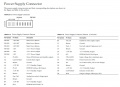 DPEx950 Pinout.jpg 1,100 × 800; 94 KB
 DPEx950 cover removed.jpg 1,024 × 576; 82 KB
 DPEx950 front insulated1.jpg 1,024 × 576; 91 KB
 DPEx950 front insulated2.jpg 1,024 × 576; 93 KB
 DPEx950 front insulated3.jpg 1,024 × 576; 78 KB
 DPEx950 ground teeth cover1.jpg 1,024 × 576; 64 KB
 DPEx950 insulator coax.jpg 1,024 × 576; 84 KB
 DPEx950 insulator coax cut.jpg 1,024 × 576; 76 KB
 DPEx950 insulator installed.jpg 1,024 × 576; 63 KB
 DPEx950 insulator installing.jpg 1,024 × 576; 71 KB
 DPEx950 negative wire inserted.jpg 1,024 × 576; 101 KB
 DPEx950 negative wire soldered.jpg 1,024 × 576; 88 KB
 DPEx950 positive teeth cover1.jpg 1,024 × 576; 88 KB
 DPEx950 positive wire soldered.jpg 1,024 × 576; 88 KB
 DPEx950 power test.jpg 1,024 × 576; 112 KB
 DPEx950 teeth spread1.jpg 1,024 × 576; 81 KB
 Direwolf AGW Client Connected.jpg 807 × 446; 110 KB
 Initialization success.jpg 646 × 360; 57 KB
 No Agwpe-ini.jpg 476 × 160; 19 KB
 Sg control.jpg 321 × 316; 37 KB
 Sg high hf off.jpg 629 × 439; 70 KB
 Sg high hf set.jpg 629 × 438; 70 KB
 Sg high vhf-set.jpg 631 × 439; 71 KB
 Sg high vhf off.jpg 631 × 439; 71 KB
 Sg input.jpg 577 × 345; 79 KB
 Sg low hf set.jpg 640 × 440; 37 KB
 Sg sm hf.jpg 229 × 166; 15 KB
 Sg sm vhf.jpg 229 × 167; 15 KB
 Site Properties.jpg 734 × 560; 108 KB
 Site Properties empty.jpg 734 × 560; 100 KB
 TK-760HG TK-862G TK-863.jpg 1,024 × 576; 106 KB


