Modifying Kenwood TK-760(H)G/762(H)G/860(H)G/862(H)G/863G for Packet Service
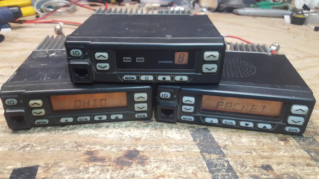
The Kenwood TK-760(H)G/762(H)G/860(H)G/862(H)G/863G are relatively low cost commercial radios that can be reprogrammed to work in the 2m and 70cm bands and depending on band and model are rated for 25-50w output. With a steady hand and fine tipped soldering iron, they can be modified for 1200-9600 baud service including optional COR/COS signaling for hardware carrier detect or use in other services like Allstarlink, Echolink, SVXLink, Repeater controllers/remote base, etc. This guide wires them to the Kantronics DB-9 standard and is compatible with the 4 port controller, details to support adaptation to other interfaces to other interfaces is included.
| Model | Band | Channel Capacity | Output Power | Subband Splits |
| TK-760G | VHF High (2m) | 128 | 25W | K = 148-174 MHz, K2 = 136-162 MHz |
| TK-760HG | VHF High (2m) | 128 | 50W | K = 148-174 MHz, K2 = 136-162 MHz |
| TK-762G | VHF High (2m) | 8 | 25W | K = 148-174 MHz, K2 = 136-162 MHz |
| TK-762HG | VHF High (2m) | 8 | 50W | K = 148-174 MHz, K2 = 136-162 MHz |
| TK-860G | UHF (70cm) | 128 | 25W | K = 450-490 MHz, K2 = 485-512 MHz, K3 = 400-430 MHz |
| TK-860HG | UHF (70cm) | 128 | 40W | K = 450-490 MHz, K2 = 485-512 MHz, K3 = 400-430 MHz |
| TK-862G | UHF (70cm) | 8 | 25W | K = 450-490 MHz, K2 = 485-512 MHz, K3 = 400-430 MHz |
| TK-862HG | UHF (70cm) | 8 | 40W | K = 450-490 MHz, K2 = 485-512 MHz, K3 = 400-430 MHz |
| TK-863G | UHF (70cm) | 600 | 25W | 1 = 450-490 MHz |
A note on Bandsplits
For VHF, the K is the most common split, but both the K and K2 splits cover all of 2m (144-148 MHz) without issue. For UHF, the K split is also the most common split (450-490 MHz) and can usually cover at least 438-450 MHz, some of them will go down as low as 433 MHz with a simple VCO adjustment. The less common K2 split (485-512 MHz) is too far away from the 70cm band to be used and should be avoided. The least common K3 split (400-430 MHz) can probably cover the lower portions of the 70cm band, possibly up to 440 or higher. We have not been able to obtain any of these to test. If you do end up with a K3 split and want a K split, please contact us[1] to arrange a trade, we will cover shipping.
Modification Process
Prior to beginning any modification, it is best to test the radio for proper functionality. If this service was purchased used, there is a fair chance it is programmed to commercial frequencies. Reprogramming into the amateur bands is possible for the TK-760(H)G/762(H)G/860(H)G/862(H)G using the KPG-56D software which is available in both DOS and Windows. The TK-863G requires KPG-76D and is available only for Windows. In general, the VHF high band versions will work well into the 2m band with little or no adjustments needed to the VCO or receiver. The UHF versions (K split, 450-490 MHz) will often work without modification in the upper 10 MHz (440-450 MHz) and sometimes lower. Many of the UHF versions can go lower into the 70cm band by adjusting the VCO circuits. Some may go down as low as 433 MHz or possibly lower. It should be possible to add small amounts of parallel capacitance across the trimmer capacitors in the VCO section to pull it's range lower in frequency. This will likely be explored in the future.
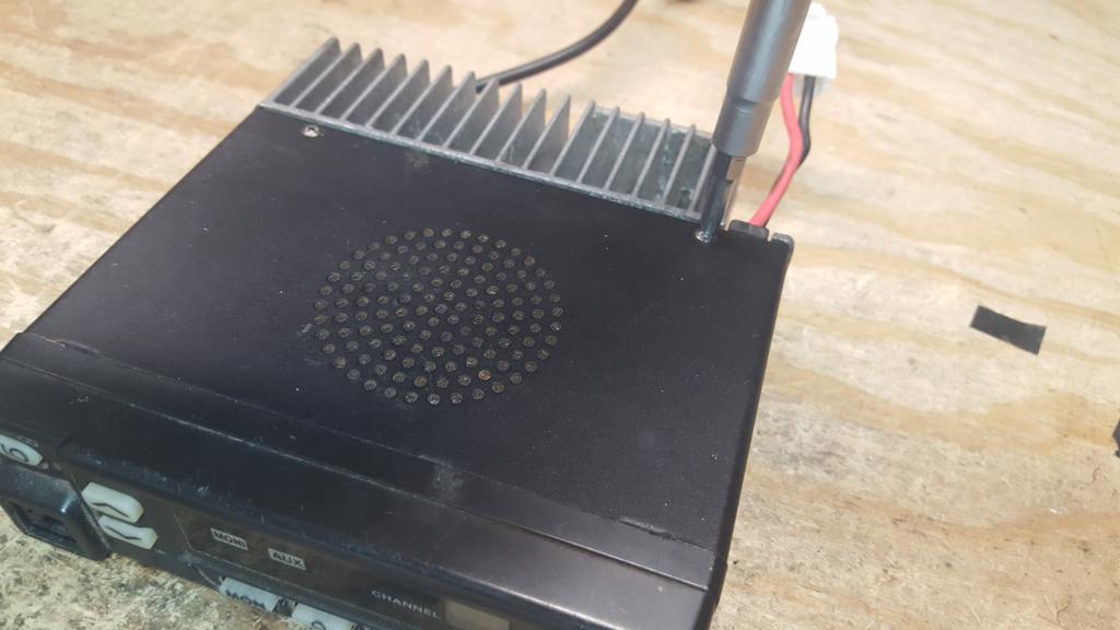
1) Open the top cover by removing the two rear screws near the heatsink
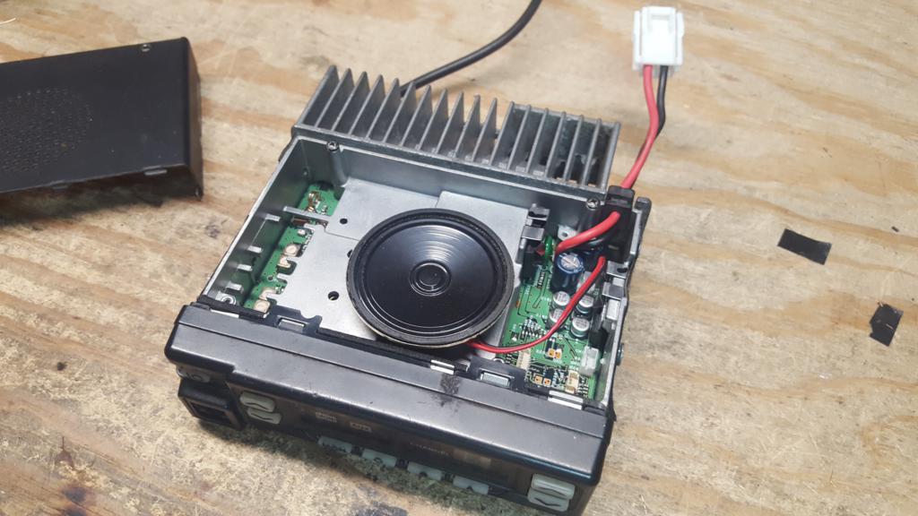 2) With the top cover removed, use a pair of pliars to gently pull out the speaker from the main board, setting the speaker aside for now.
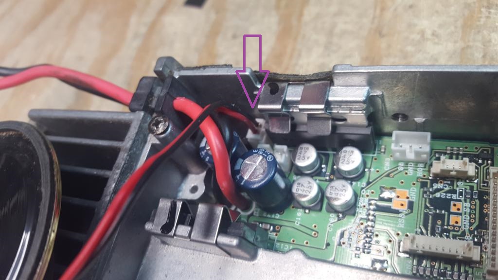
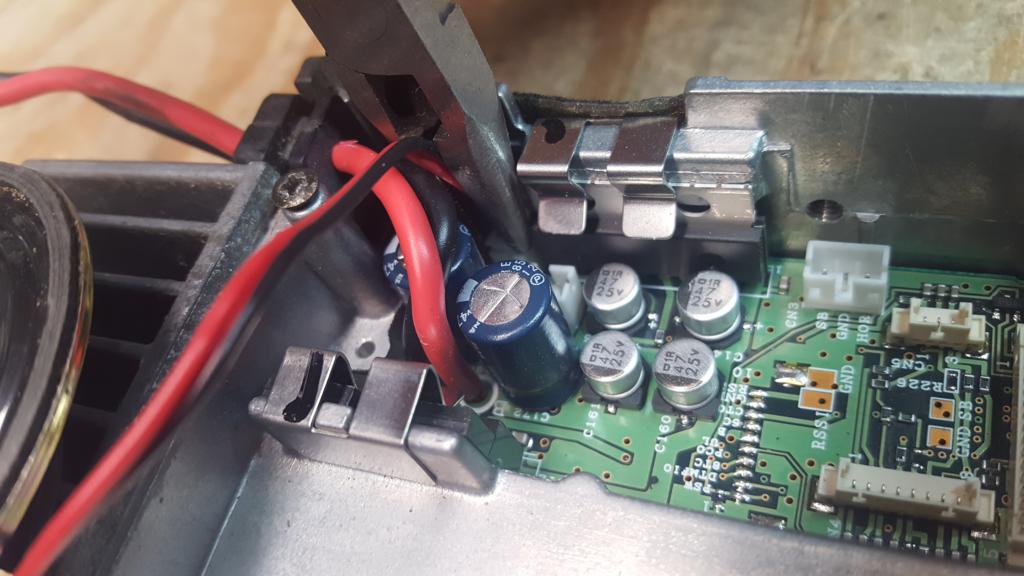
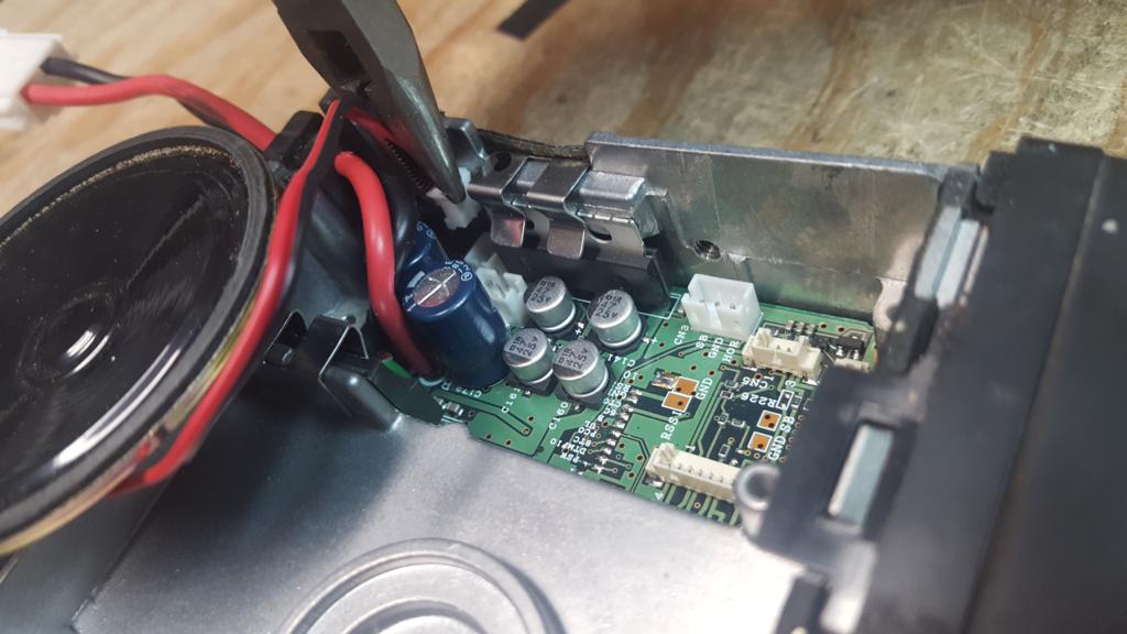 3) Flip the radio over and remove the two rear screws near the heatsink
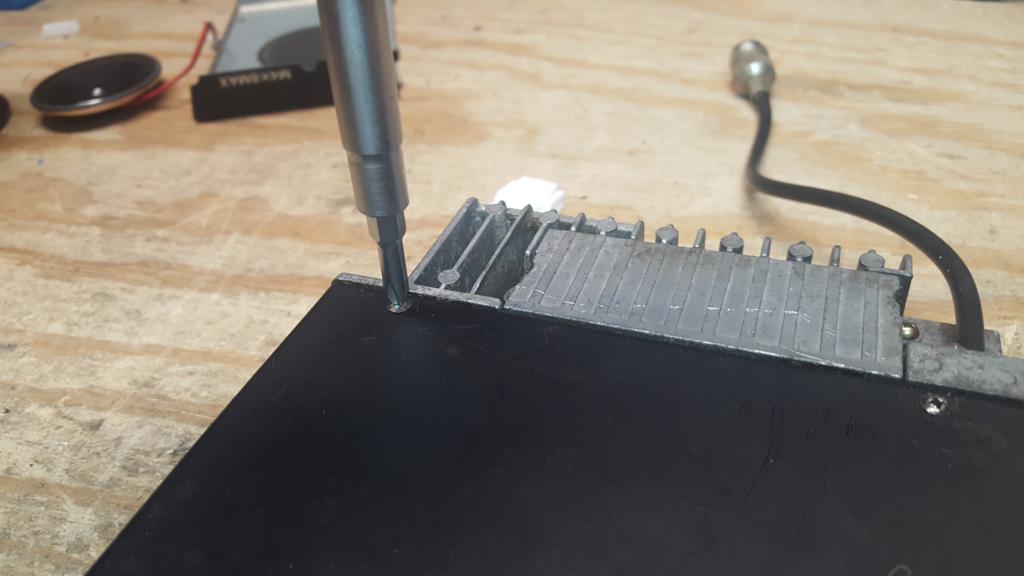
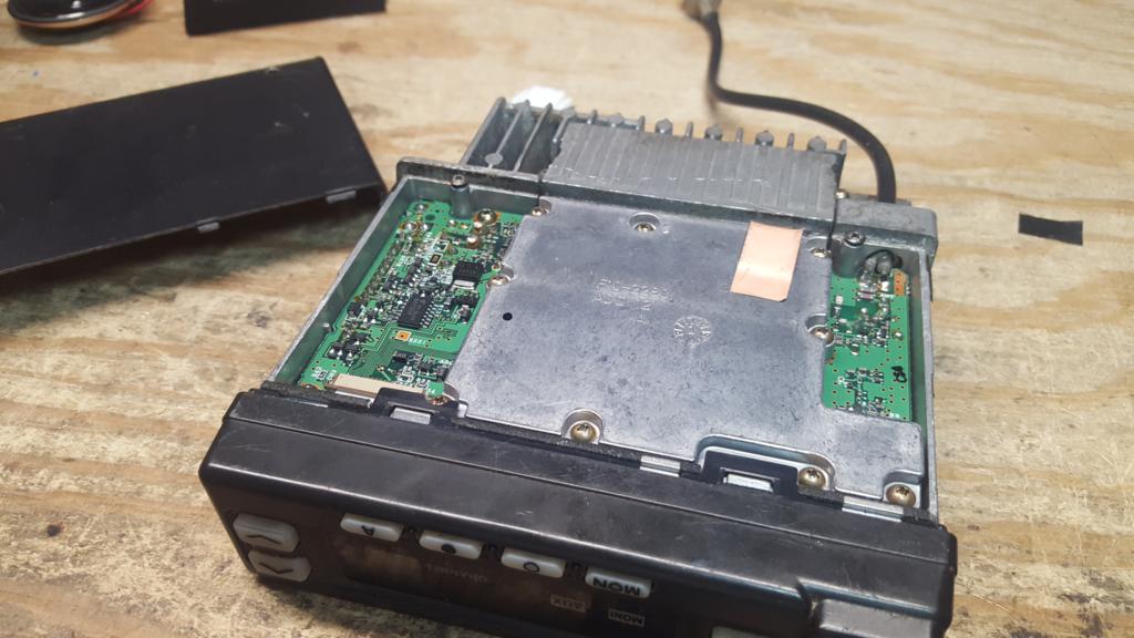 4) Gently lift up on the tabs on the faceplate and slide forward
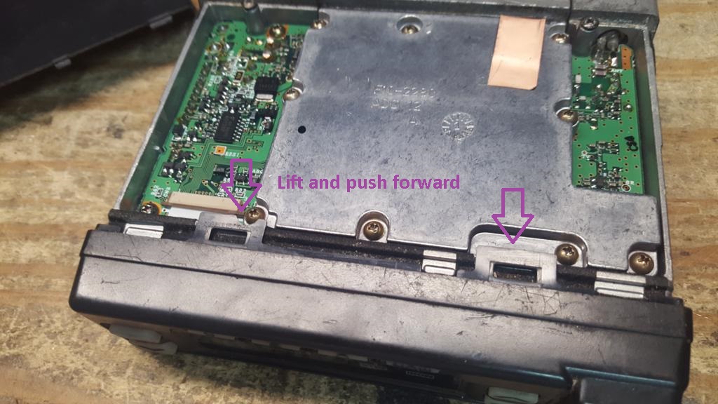 5) Flip the radio over and lift up on the tabs on the faceplate and slide forward
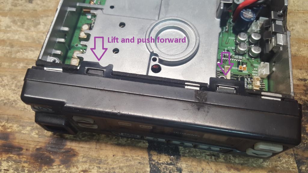
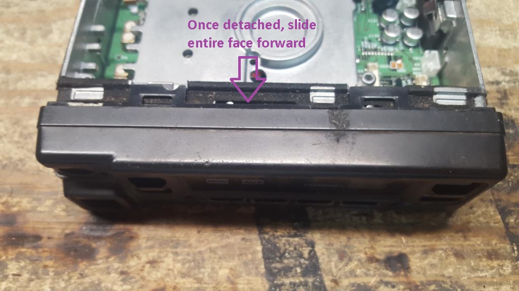
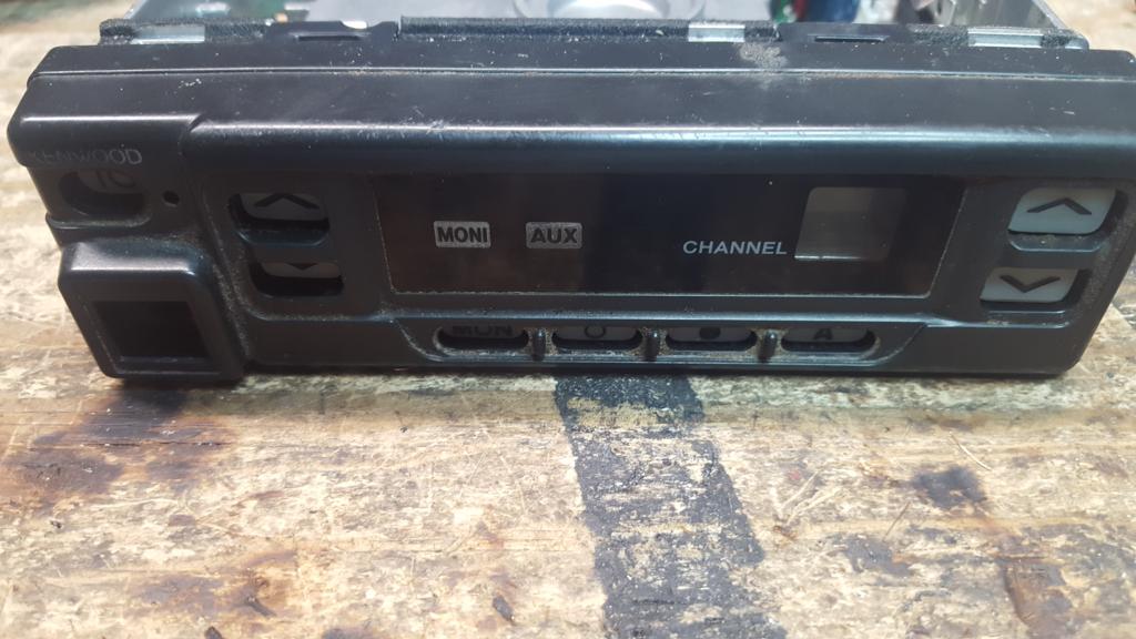 6) Pull the faceplate forward, there is a rubber membrane for the keys which may separate from the faceplate or remain in the faceplate. Separated membrane shown.
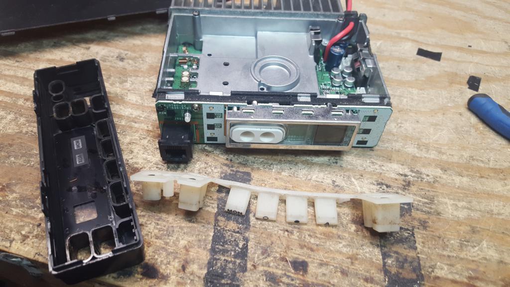 7) Remove the two faces which hold on the faceplate circuit board
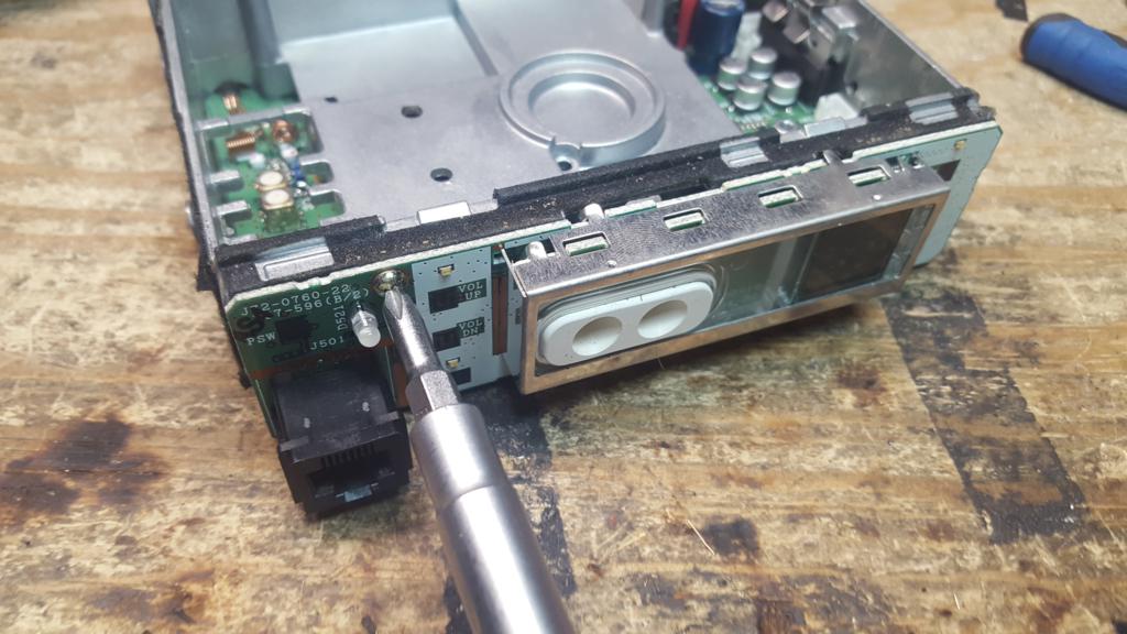
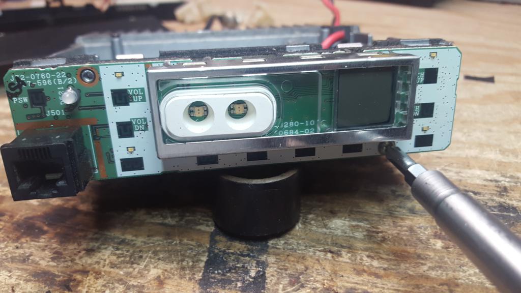 8) Gently pull the faceplate circuit board forward, it may be somewhat "stuck" to the chassis, be careful not to pull to hard which could damage the ribbon to the main board.
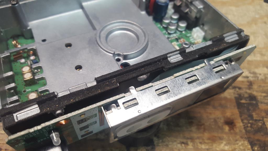
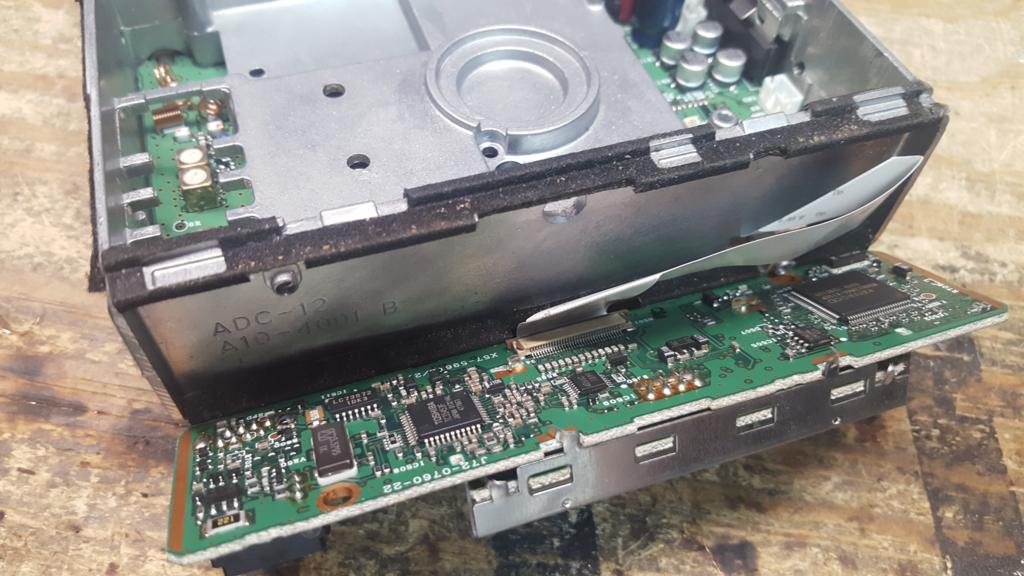 9) Lay the faceplate circuit board down, exposing the solder side
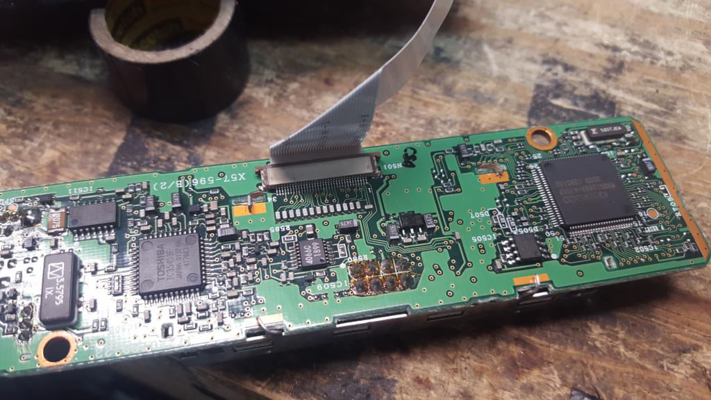 10) Carefully pull up the brown tabs on either side of where the ribbon cable locks into the faceplate circuit board
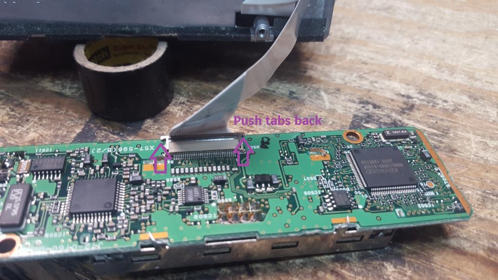 11) Pull the ribbon cable away from the faceplate circuit board.
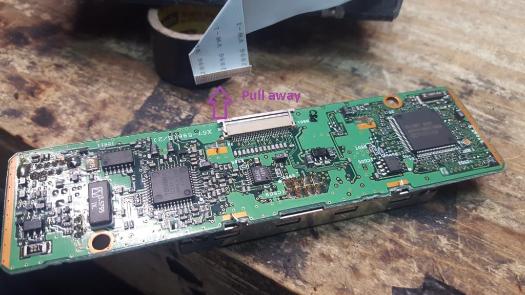 12) Flip the faceplate circuit board to where the ribbon cable attachment faces down
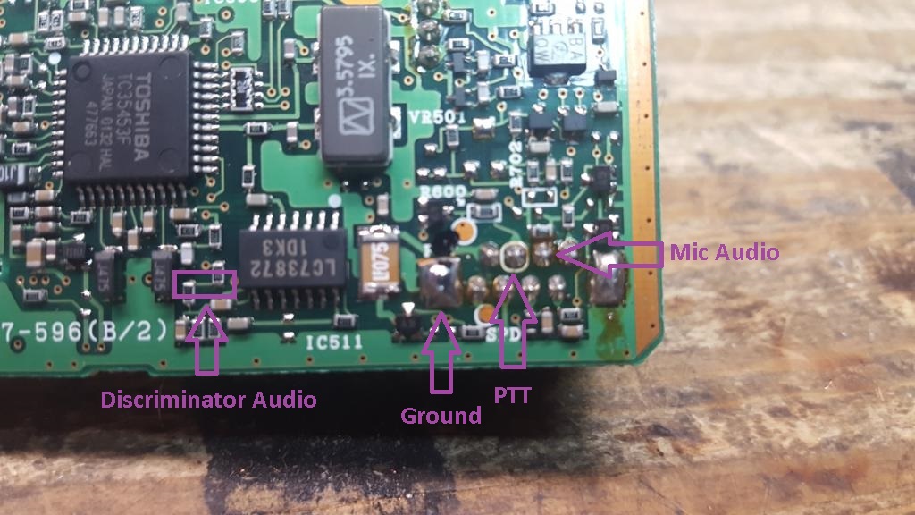
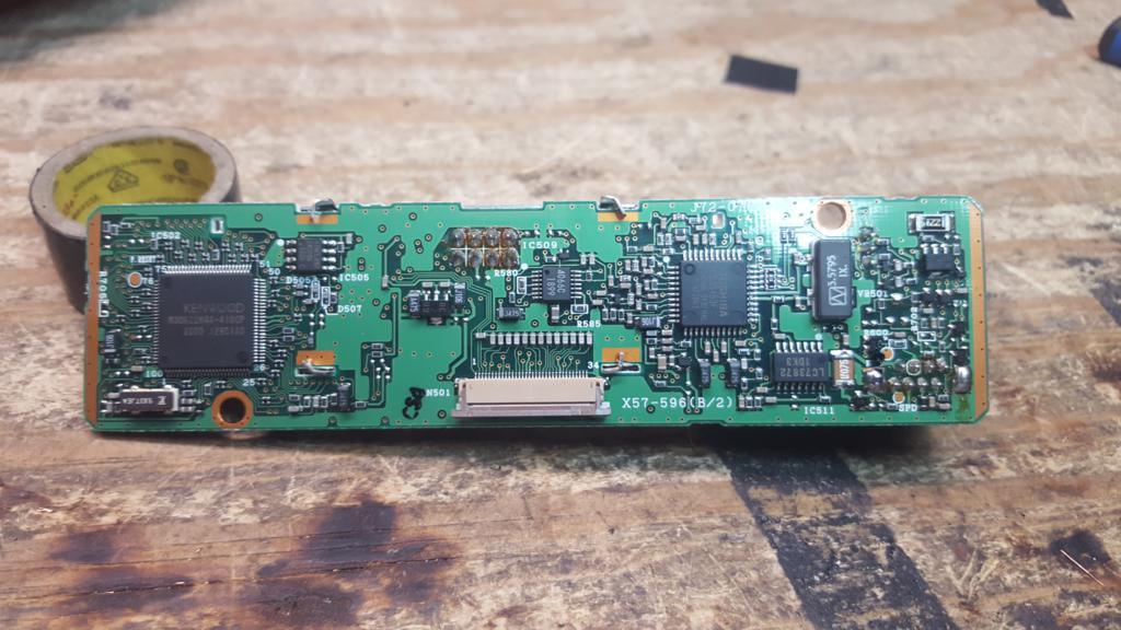 13) Our area of interest is on the bottom right side of the faceplate circuit board
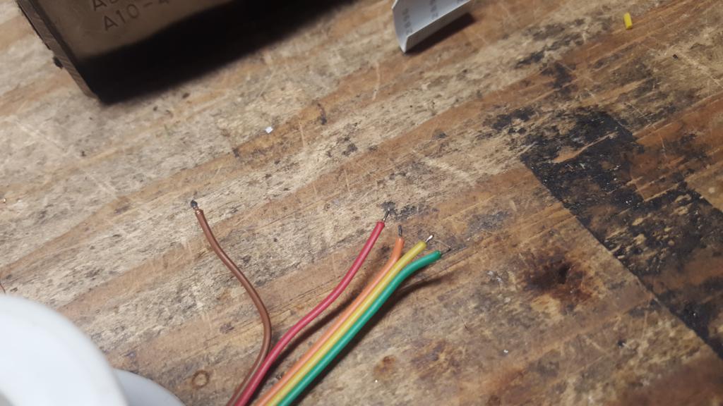
 14) Cut about 5 inches of 5 conductor ribbon cable. If you want to have support for COR signaling strip back about 1/8" of all 5 wires, twist and tin. If you do not want to add COR support (not required for packet) strip back about 1/8" of 4 wires, leaving one unstripped or it can be removed completely. In this guide we will show COR support. Separate 2 of the 5 wires several inches, the separation of the remaining 3 can be left short. In this build
Green = PTT Yellow = TX Audio Orange = Ground Red = RX Audio (Discriminator) Brown = COR (Active high)
 15) Solder the PTT wire to the second from left pin behind the microphone jack
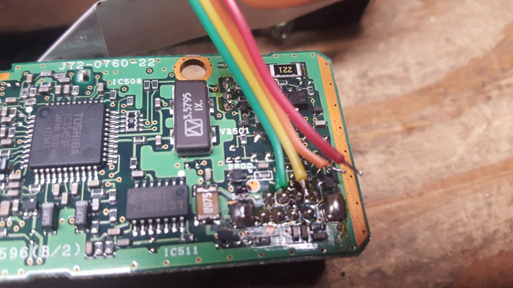 16) Solder the TX Audio wire to the third from left pin, next to the PTT wire
File:TK-n6ng TXAudio soldered.jpg
17) Repositioning the wire, solder the ground wire to the grounding pad below the microphone jack to the left
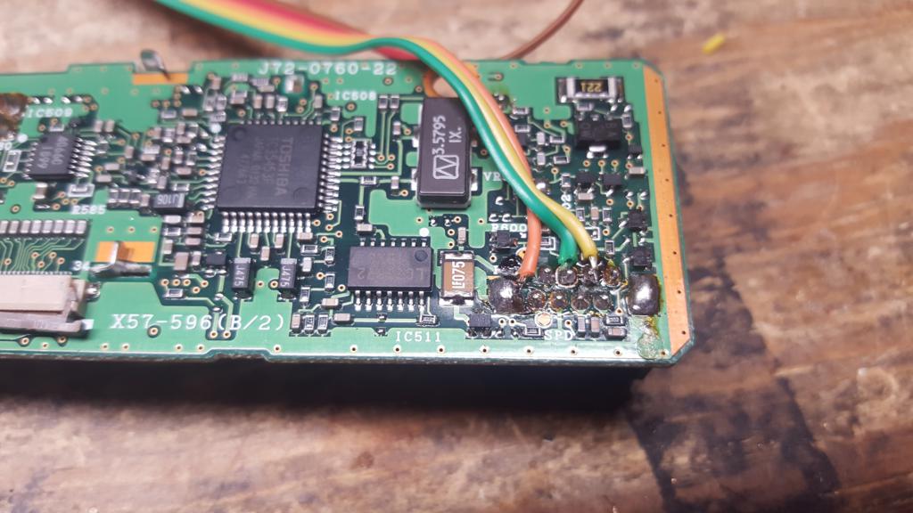 18) Carefully apply solder to one of the two surface mount resistors that carry Discriminator audio
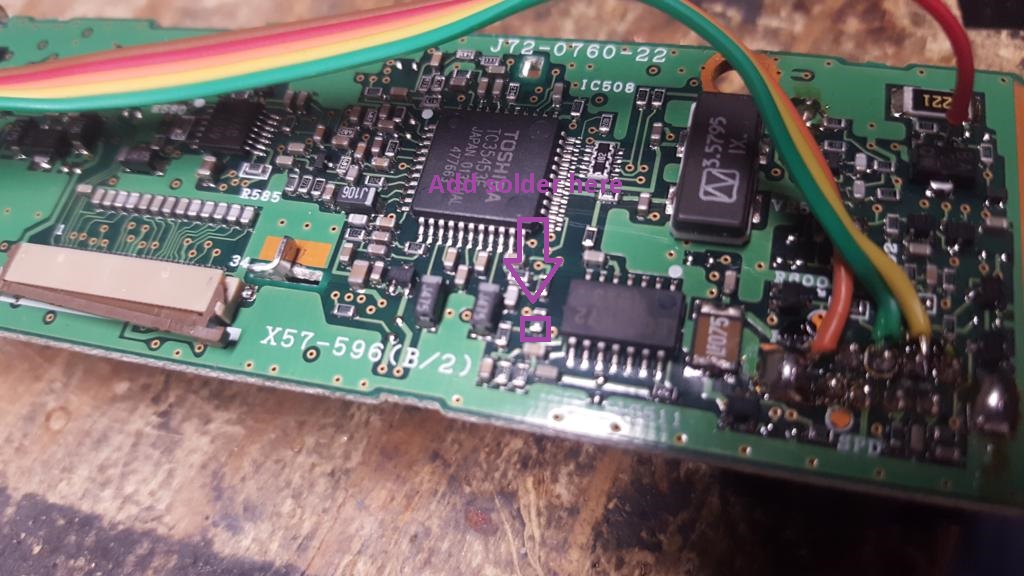 19) Add a bit more solder to the tip of the RX audio wire
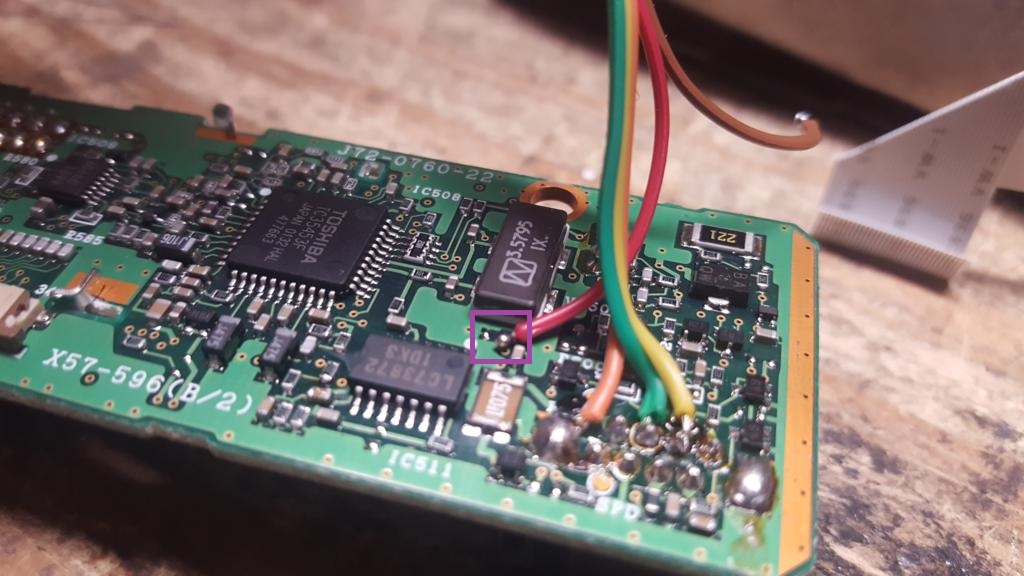 20) Carefully hold the tinned RX audio wire over the surface mount resistor and apply heat, the goal is to melt the extra solder to flow over the resistor
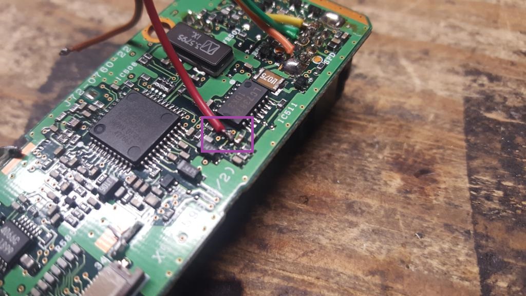 21) Using electrical tape or some other method, apply strain relief on the RX audio wire to try and keep any mechanical stress off the solder joint.
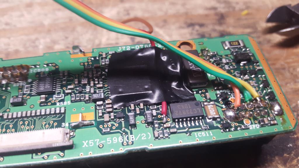 22) Feed the ribbon cable through the small hold in the top/center of the chassis to the main body of the radio. The COR wire is still "floating" at this point.
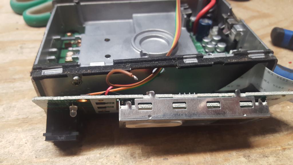 22) Pull away the COR wire, this will be fed to the opposite corner of the face plate to be passed next to the ribbon cable to the under side of the radio. This will split about where the ribbon cable passes through to the main body of the radio.
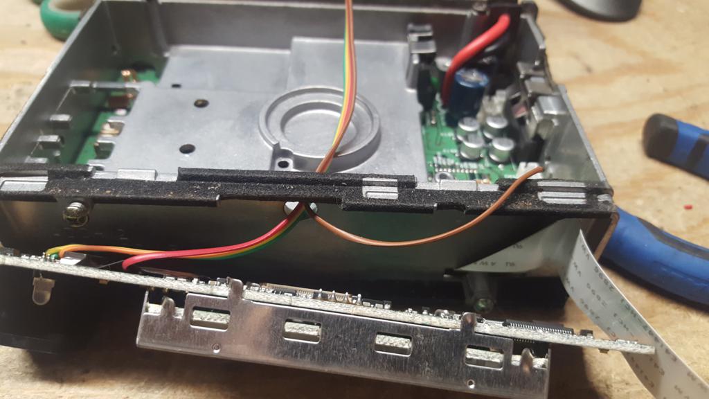 23) Feed the COR wire through the small opening in the chassis that passes the thin ribbon cable between the face plate and main board
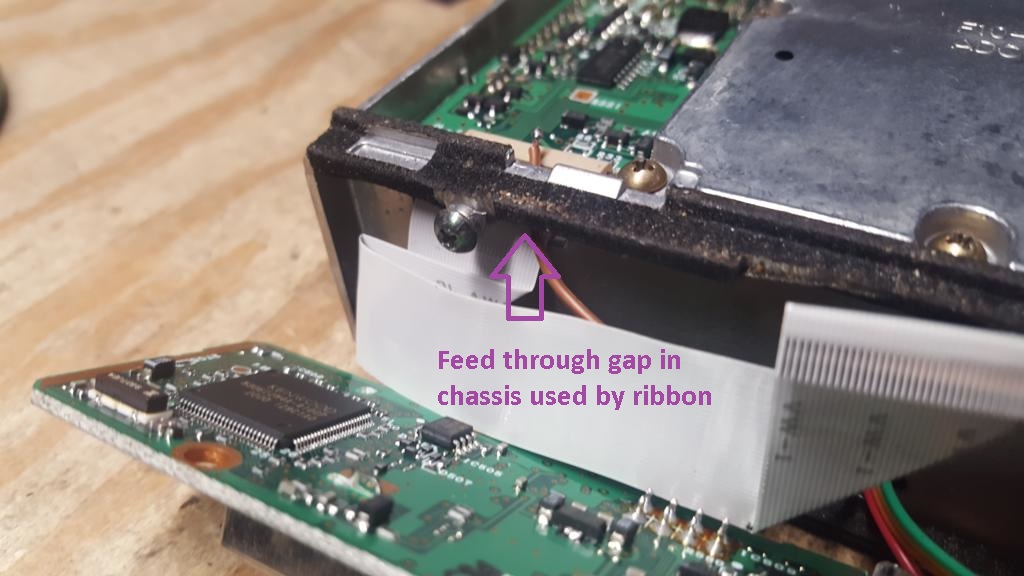
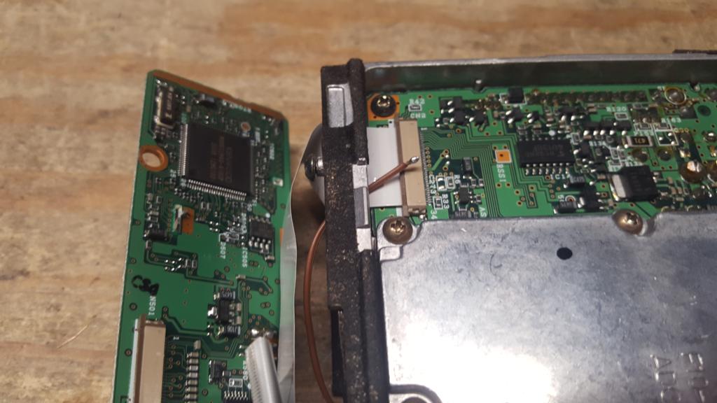 24) Side the face plate circuit board back towards the main chassis of the radio, lining up the ribbon cable with the attachment point.
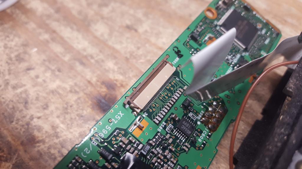 25) Slide the ribbon cable back into position. Be sure to press inward to try and get the ribbon cable fully seated.
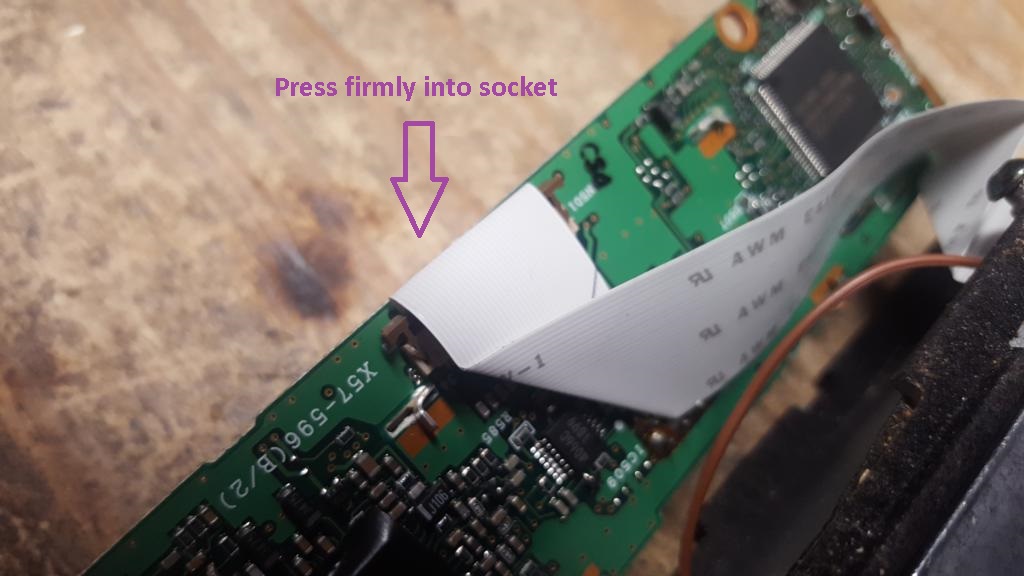 26) Gently press down on the brown tabs on either side to lock the ribbon cable in place.
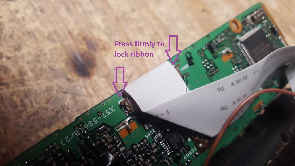 27) Press the faceplate circuit board back against the main chassis. Be careful not to pinch any of the wires we soldered in the process and that the COR wire remains visible in the under side of the radio. Reattach the first screw holding the faceplate circuit board.
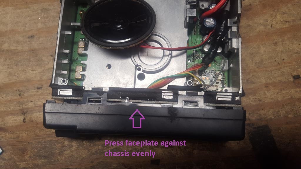 28) Flip the radio over and attach the second screw holding the faceplate circuit board.
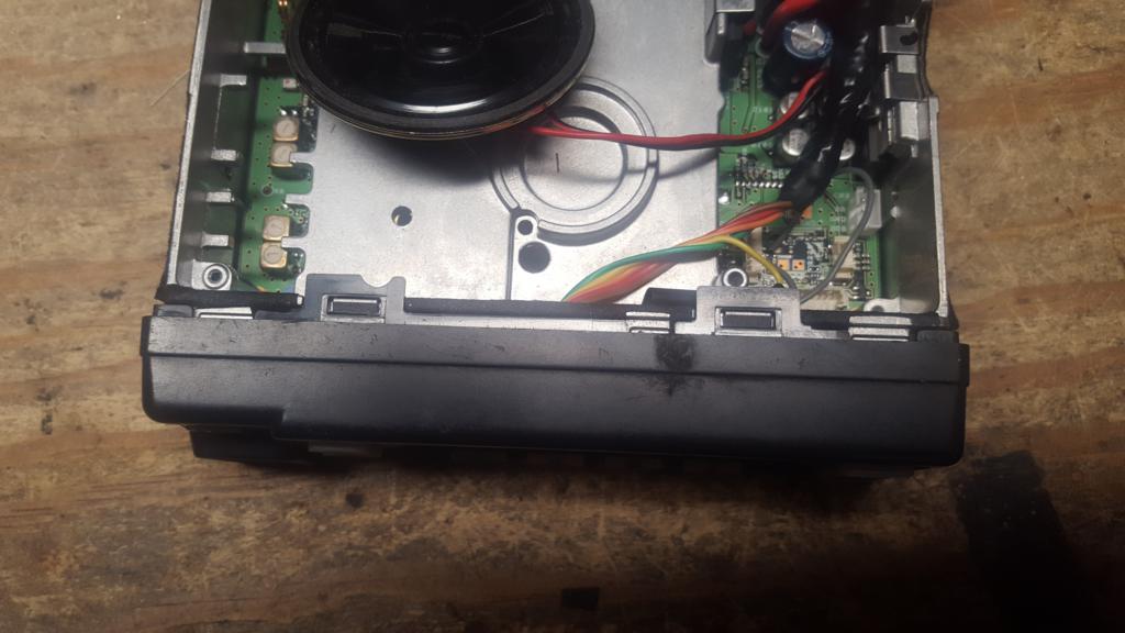 29) If COR signaling is desired, flip the radio over putting the side with the COR wire fed to the front. This is where our COR circuit will be attached. If COR signaling is not desired, skip to step XXX
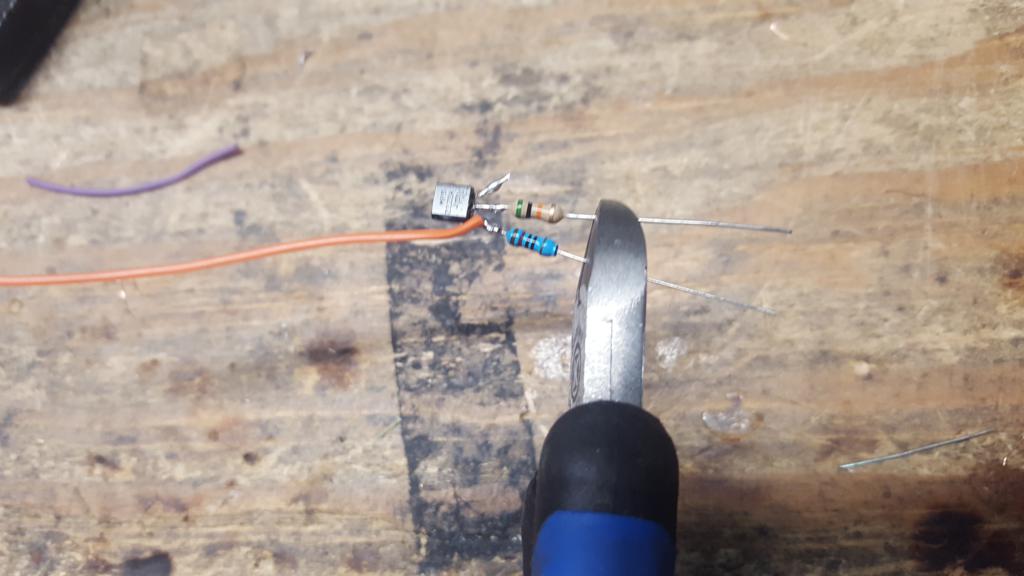
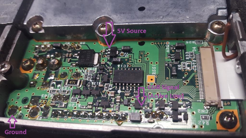 30) Take a 2n2222 or equivalent transistor, 10k resistor and 50k resistor. These will allow us to invert the COR logic, which is natively active low to be active high. We want to attach the 10k resistor to the emitter and 50k resistor to the base.
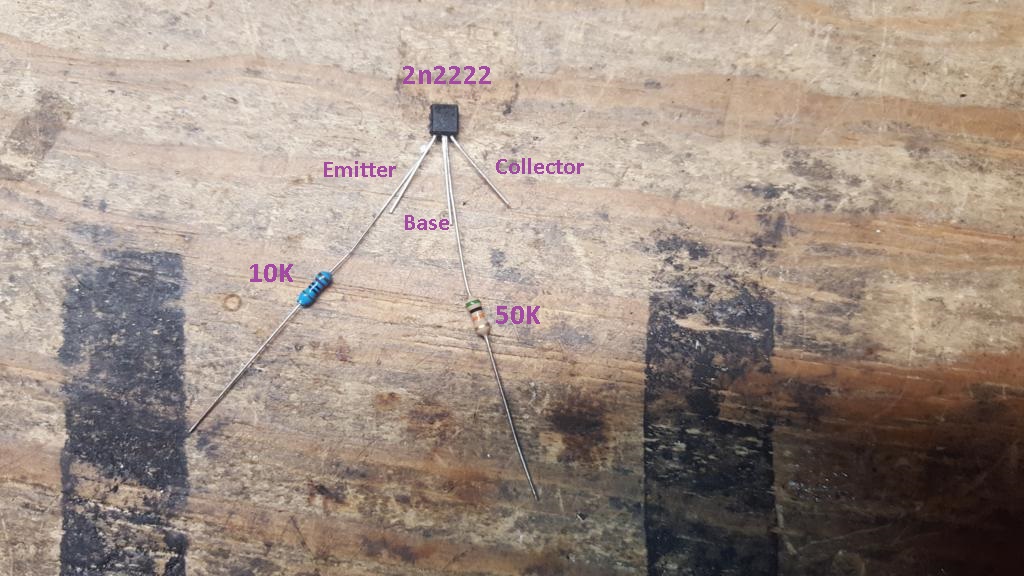 31) Trim the leads on the 2n2222 to about 1/4" on all the leads.
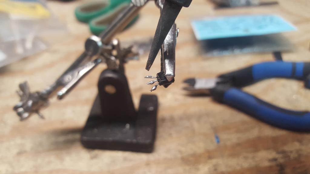
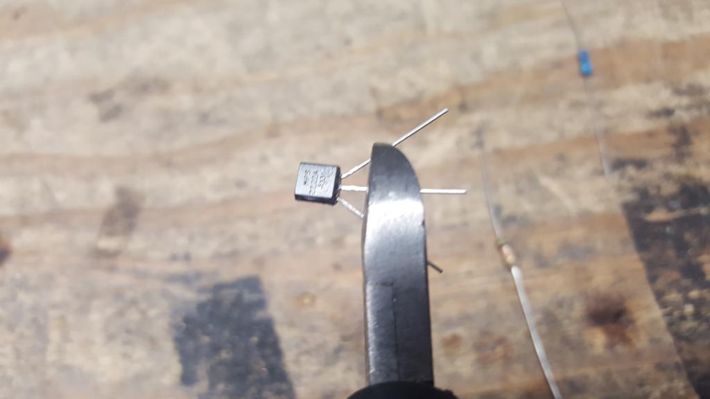 32) Apply solder to all 3 leads on the 2n2222
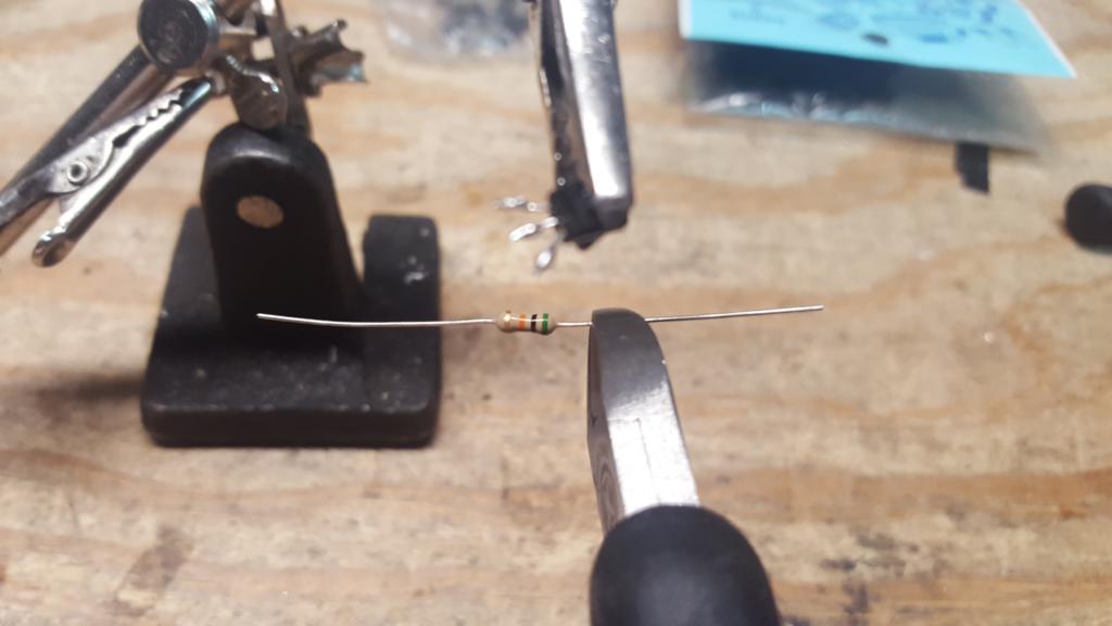
 33) Trim one of the leads on the 50k resistor to about 1/4" and tin the lead.
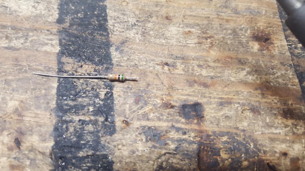 34) Solder the 50k resistor to the base (center wire) of the 2n2222.
File:TK n6ng COR 50k to 2n2222.jpg
35) Trim one of the leads on the 10k resistor about 1/4" and tin the lead.
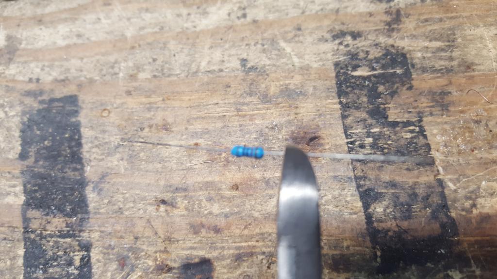
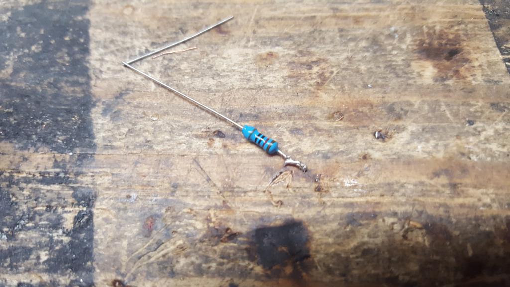 36) Solder the 10k resistor to the emitter (left of base pictured) of the 2n2222.
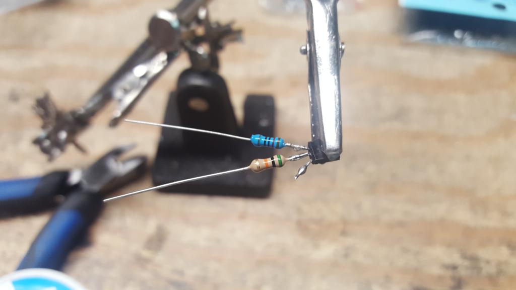 37) Take about 2" of single wire from the ribbon cable to be use for COR logic inverter output, strip back about 1/4" but do not tin. In this example we will use an orange wire.
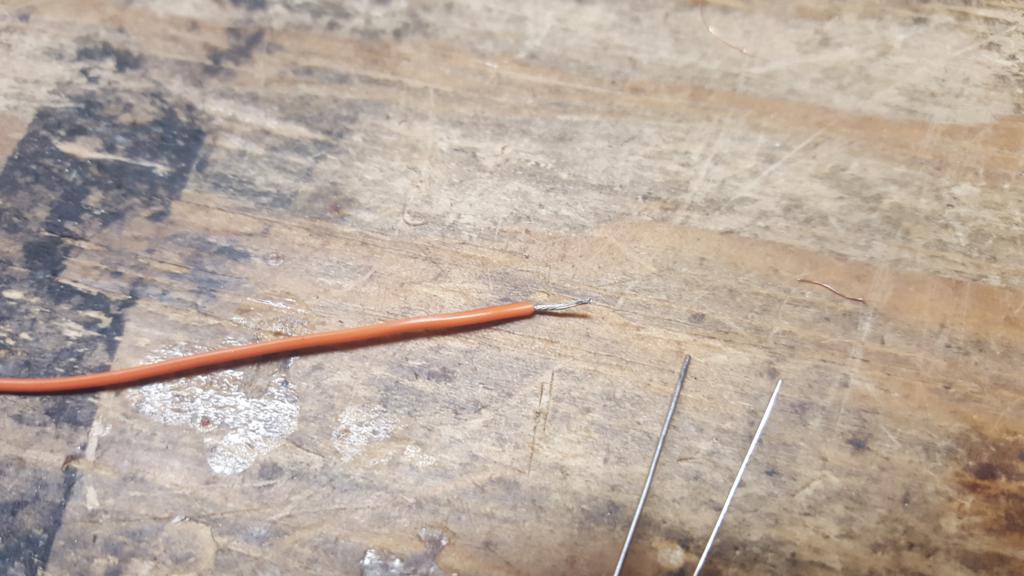 38) Take the stripped end of the COR logic inverter output and wrap it around the soldered connection between the 10k resistor and 2n2222 emitter.
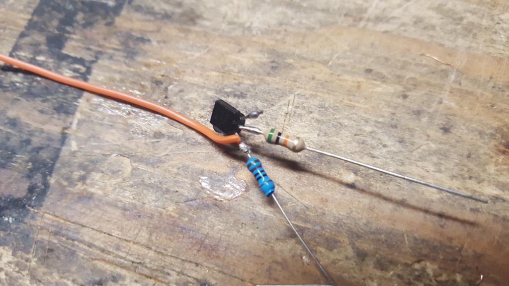 39) Solder the COR logic inverter output wire around the 2n2222 and 10k resistor junction as shown.
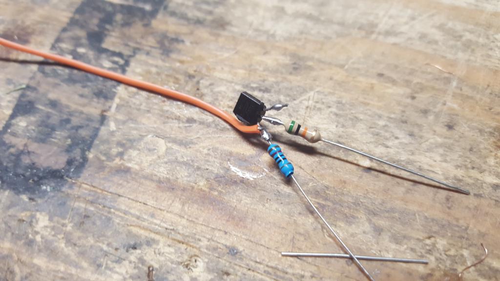 40) Trim both the 10k and 50k resistor legs about 1/4" on the opposing lead that is soldered to the 2n2222.
