Modifying Kenwood TK-760(H)/762(H)/860(H)/862(H) for Packet Service
The Kenwood TK-760(H)/762(H)/860(H)/862(H) are relatively low cost commercial radios that can be reprogrammed to work in the 2m and 70cm bands and depending on band and model are rated for 25-45w output. With a steady hand and fine tipped soldering iron, they can be modified for 1200-9600 baud service, VARA FM/FM Wide, including optional COR/COS signaling for hardware carrier detect or use in other services like Allstarlink, Echolink, SVXLink, Repeater controllers/remote base, etc. This guide wires them to the Kantronics DB-9 standard and is compatible with the 4 Port packet controller and NinoTNC, details to support adaptation to other interfaces/TNCs/controllers is included.

| Model | Band | Channel Capacity | Output Power | Subband Splits |
| TK-760 | VHF High (2m) | 32 | 25W | 1 = 148-174 MHz, 2 = 136-156 MHz |
| TK-760H | VHF High (2m) | 32 | 45W | 1 = 148-174 MHz, 2 = 136-156 MHz |
| TK-762 | VHF High (2m) | 2 | 25W | 1 = 148-174 MHz, 2 = 136-156 MHz |
| TK-762H | VHF High (2m) | 2 | 45W | 1 = 148-174 MHz, 2 = 136-156 MHz |
| TK-860 | UHF (70cm) | 32 | 25W | 1 = 450-476 MHz, 2 = 470-496 MHz, 3 = 488-512 MHz, 4 = 406-430 MHz |
| TK-860H | UHF (70cm) | 32 | 35W | 1 = 450-476 MHz, 2 = 470-496 MHz, 3 = 488-512 MHz, 4 = 406-430 MHz |
| TK-862 | UHF (70cm) | 2 | 25W | 1 = 450-476 MHz, 2 = 470-496 MHz, 3 = 488-512 MHz, 4 = 406-430 MHz |
| TK-862H | UHF (70cm) | 2 | 35W | 1 = 450-476 MHz, 2 = 470-496 MHz, 3 = 488-512 MHz, 4 = 406-430 MHz |
A note on Bandsplits
The band splits are indicated differently between some documentation and what is actually printed on the radio. The labels on the radio seem to be numeric while the documentation references the letter K. Cross referencing the two:
K, HK = 1
K2, HK2 = 2
K3, HK3 = 3
K4, HK4 = 4
For VHF, the K(1) is the most common split, but both the K(1) and K2 splits cover all of 2m (144-148 MHz) without issue. For UHF, the K(1) split is also the most common split (450-470 MHz) and can usually cover at least 438-450 MHz, some of them will go down as low as 430 MHz with a simple VCO adjustment. The less common K2 (470-496 MHz) and K3 (488-512 MHz) splits are too far away from the 70cm band to be used and should be avoided except for part donors. The least common K4 split (406-430 MHz) can probably cover the lower portions of the 70cm band, possibly up to 440 or higher. We have not been able to obtain any of these to test, though they be may more available in proximity to Line A along the northern border of the USA and up in Canada where it is a commercial band. If you do end up with a K4 split and want a K split, please contact us to arrange a trade, we will cover shipping in both directions.
Required parts
1) Around 12" of 6 or more conductor ribbon cable, multicolor suggested
2) 34" of Devicenet 2 pair 22 gauge cable
3) 1-2x 3 pin 2.54mm header, commonly available for Raspberry Pi and Arduino projects (Optional 1 for COR logic signaling enable/disable and/or changing TX audio between mic and modulator input)
4) 1-2x 2.54mm jumper (Optional for connections on item 3)
5) 1/8" heatshrink tubing
6) 1/4" heatshrink tubing
7) DB9 male, solder cup type suggested
8) DB9 hood, metal plated suggested
9) Electrical tape
10) Fine tipped soldering iron and solder
11) #1 or #2 Phillips screwdriver
12) Edge wire cutters
13) Box cutter or similar knife
14) Wire stripper for 22awg wire (optional)
15) Multimeter for testing (optional)
Modification Process
Prior to beginning any modification, it is best to test the radio for proper functionality. If the radio was purchased used, there is a fair chance it is programmed to commercial frequencies. Reprogramming into the amateur bands is possible for the TK-760(H)G/762(H)G/860(H)G/862(H)G using the KPG-29D software which is available for DOS only. In general, the VHF high band versions will work well into the 2m band with little or no adjustments needed to the VCO or receiver. The UHF versions (K split, 450-470 MHz) will often work without modification in the upper 10 MHz (440-450 MHz) and sometimes lower. Many of the UHF versions can go lower into the 70cm band by adjusting the VCO circuits. Some may go down as low as 430 MHz or possibly lower. It should be possible to add small amounts of parallel capacitance across the trimmer capacitors in the VCO section to pull it's range lower in frequency. This will likely be explored in the future.
1) Open the top cover by removing the four screws near the heatsink and face of the radio


2) Lift the speaker and plastic speaker mount off the chassis and set both off to the side.

3) Use a pair of pliers to gently pull out the speaker from the main board, setting the speaker aside for now.


4) Flipping the radio over, remove the bottom cover by removing the four screws near the heatsink and face of radio


6) Flipping the radio back over, gently lift up on the plastic tabs and push the faceplate forward.


5) Flipping the radio over again, gently lift the plastic tabs attached to the faceplate and slide the faceplate forward.

7) Pull the faceplate away from the chassis to expose the faceplate circuit board

8) Gently apply pressure to the brown tabs holding the flat ribbon cable to the back of the faceplate circuit board
[[File:TK-n6n_faceplate_ribbon_tab_unlocked.jpg|320px]
9) With the tabs up, pull the ribbon out of the connector on the back of the faceplate circuit board.


10) Remove the 4 screws holding the faceplate circuit board to the faceplate.


11) With the screws removed, flip the faceplate over putting the circuit board down and display and buttons up. The faceplate circuit board may begin to slide backwards, apply gentle pressure to the buttons to help free the circuit board if needed.

12) On the TK-n62(H) radios only, there will be a foam insert that sits between the faceplate and faceplate circuit board. This can be brittle so carefully lift it off the board.

13) Pull away the rubber membrane that makes up the buttons and set it off to the side

14) Flipping the solder side of the front faceplate circuit board forward, examine the noted points for connection. The COR, Discriminator and Microphone Input lines all have convenient solder pads for connections. The PTT must be soldered to the pin on the rear of the RJ-6 connector. The Modulator input is soldered to the left side of the capacitor near the microphone connector. On some newer models, there may be a small solder pad just below the Modulator Input capacitor for a convenient solder pad.

15) Cut about 8" of 6 conductor ribbon cable, multicolor is suggested. In this build the following colors are used:
Brown = COR
Black = Discriminator Audio
White = Ground
Grey = Modulator Input
Purple = PTT
Blue = Microphone Input
16) Separate the COR and Discriminator audio lines from the ribbon cable. Strip and tin about 1/8" on the COR cable.

17) Apply a small amount of solder to the COR, Discriminator and Microphone Input pads


When finished they should look like this:


18) Solder the COR wire to the COR solder pad

19) Separate the discriminator audio wire and cut it to length to be soldered on the discriminator audio pad.


20) Strip about 1/8" and tin the discriminator audio wire

21) Solder the discriminator audio wire to the solder pad

22) Separating the remaining ribbon cable, fold the wires as shown to run the ground wire (white) along the grounding pad on the rear of the microphone conenctor

23) Cut the ground wire to length so it can be soldered to the large grounding pad

24) Strip and tin about 3/16" of the ground wire

25) Solder the ground wire to the grounding pad

26) Apply more solder to the modulator input capacitor. If the radio has a solder pad below the capacitor, apply more solder to that pad instead.


27) Feeding the remainder of the ribbon cable through, line up the modulator input wire next to the modulator input capacitor or solder pad, cutting to length.

28) After cutting the modulator wire, strip and tin about 1/8" from the wire

29) Solder the modulator wire to the capactitor or solder pad if present.

30) Apply solder to the PTT pin on the back of the faceplate circuit board. It will be the top row, center pin


Post modification testing
Multimeter + Second radio testing:
1) Take a continuity tester and verify a DC short between the DB9 pin number 6 and the radio chassis as well as DB9 shell
2) Measure for DC voltage across DB9 pin number 3 (PTT). If present, attach suitable antenna or dummy load to modified and short pin 3 to the DB9 shell or DB9 pin 6, this should cause the radio to transmit.
3) Measure AC voltage across DB9 pin 5. This is discriminator receive audio and will be a fairly steady AC voltage with no signal present. If AC voltage is measured and another transmitter is available, transmit a dead carrier with no audio, this should cause the AC voltage to drop significantly if not fully near 0 volts indicating the receiver has a full quieting signal.
4) If the COR circuit was added and COR enable jumper was placed, measure DC voltage across DB9 pin number 2. With no signal present, the DC voltage should be near 0. Using either the MON function on the front of the radio OR using a secondary transmitter on the frequency, open up the squelch and this pin should read about 5VDC.
5) Create a short between DB9 pin numbers 1 (TX Audio) and 5 (RX Audio). On an secondary receiver, tune to the modified radio transmit frequency. Short DB9 pin 3 to ground either on the DB9 shell or DB9 pin 6. This should cause the radio to transmit and the secondary receiver should pick up a signal with static. Momentarily break the short between DB9 pin numbers 1 and 5, this should turn the signal from full quieting and static off the discriminator.
Soundcard interface/packet controller/hardware TNC testing:
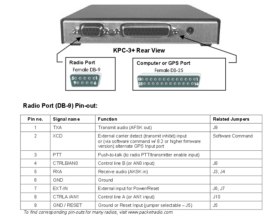
1) Attach the radio to a compatible interface. If the interface/TNC does not use the Kantronics DB9 standard, a suitable adapter will need to be made. To review, the DB9 pinout is:
DB9 Pin 1 = TX Audio
DB9 Pin 2 = COR (Active High) - if built and enabled
DB9 Pin 3 = PTT (Active Low)
DB9 Pin 5 = RX Audio
DB9 Pin 6 = Ground
2) Place the modified radio on a known packet frequency. If none is available on VHF, a good candidate for traffic is the national APRS frequency, 144.390 MHz in North America, 144.80 in Europe. Optionally turn up the volume on the radio and listen for packet bursts to come out of the speaker. When a packet burst is heard, check the interface/TNC for a successful decode.
3) Placing an auxiliary receiver on the radio transmit frequency, issue an outbound connection and listen for a packet burst on the auxiliary receiver. If no other station exists, a dummy call can be used:
C XX1XX
Please contact us any modification questions or suggestions regarding this modification process.