Modifying Dell PowerEdge 1950/2950 Power Supplies for Amateur Service
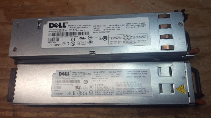
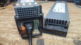
The Dell PowerEdge 1950 and 2950 power supplies offer a low cost option for providing a 12VDC and high current for a packet system or other equipment. At the time of this writing, both versions are available for under $20USD with free shipping from a popular online auction site. Both power supplies use the same pinout and can be pressed into amatuer service with 2 or 3 2.54mm jumpers or equivalent pin shorting mechanism. The Dell PowerEdge 1950 supply is rated up to 54.4 amps and the 2950 supply is rated up to 62.4 amps on their respective 12v rails.
Details on the modification
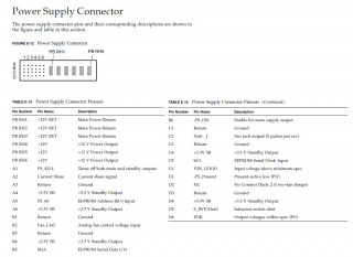
The modification using 2.54mm jumpers is very straight forward. In order to switch the power supply onto the "on" position, a short must be created from pins D1 (PS_Present) and B6 (PS_On) to ground. Optionally, shorting pin B2 (Fan_Ctrl) to ground will lower the speed of the onboard fan, greatly reducing the noise created by the power supply when running. This is recommended on the 2950 power supply if it is to be used in an operating position where a loud fan is undesirable. Removing this jumper will run the onboard fan faster and louder, but may be appropriate for installations where climate control is not possible and maximum cooling is required.
With those pins shorted, all that is left is connecting a suitable DC power lead or leads to the "teeth" of the power supply to a suitable connector. In this example, a 10awg wire connected to Anderson Powerpoles will be used.
The Modification
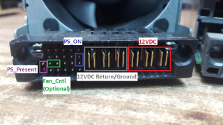
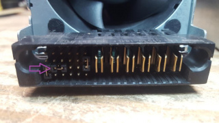
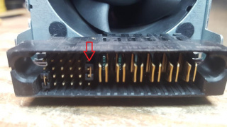
1) Face the power supply with pins facing forward. We want to place jumpers across these pins noted in Magenta and Purple, then optionally Green to reduce the fan speed.
2) Place the first jumper over pins D1 and C1
3) Place the second jumper over pins C2 and C3 if lower speed fan is desired (Optional)
4) Place the third jumper over pins B6 and C6
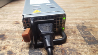
5) Plug in 115VAC to the power supply and watch for the power supply to turn on.
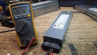
The PowerEdge 1950 will look like this:
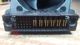
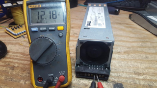
The PowerEdge 2950 will look like this:
6) If a multimeter is available, attach the ground side to any of the Ground "teeth" and positive lead to the +12VDC "teeth" and measure output. This may vary some but should fall somewhere near the 12.1-12.4VDC range.
On the example PowerEdge 1950 supply, it measured 12.32VDC
On the example PowerEdge 2950 supply, it measured 12.18VDC
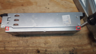
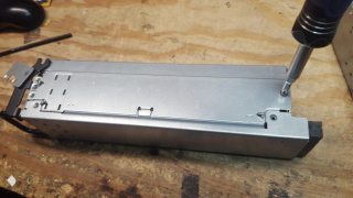
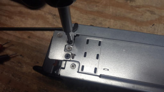
7) If higher voltage is desired on the PowerEdge 2950 power supply only, there is an internal potentiometer which can be adjusted to slightly increase or decrease voltages on the 12V rail. If using a PowerEdge 1950 or power adjustment is not needed, skip to step 16. If this is preferred, make sure that 115VAC is removed from the power supply and flip the PowerEdge 2950 supply where the ejection handle bracket is facing upwards and remove the marked screws:
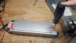
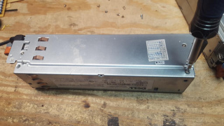
8) Flipping the power supply with it's top upwards, remove the marked screws:
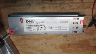
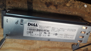
9) Flipping the power supply onto the side opposite the ejection handle bracket, remove the marked screws:
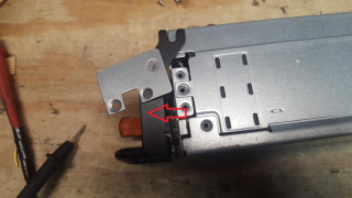
10) Returning the power supply with the ejection handle side upwards, slide the ejection handle off away from the main chassis
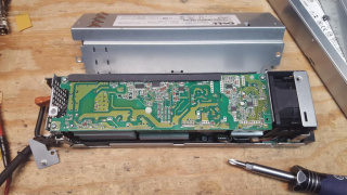
11) Lift the top of the power supply off and set the cover off to the side
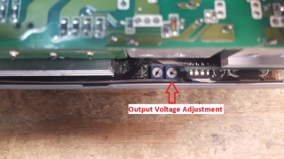
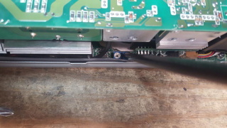
12) On the side where the ejection handle was removed, there will be a pair of potentiometers near the bottom of the supply. The potentiometer closest to the pins and teeth will adjust output power on the 12V rail.
13) Using an appropriate screwdriver or adjustment tool, gently turn the potentiometer, in the example 2950, turning the potentiometer counterclockwise raised the voltage and turning the potentiometer clockwise lowered the voltage.
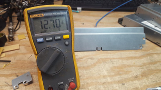
14) With this adjusted, carefully reapply 115VAC to the power supply and measure it's DC output again. Please be careful if the top is off of the power supply, there is potential for electrocution if you come in contact with the power supply internal circuitry. In the example supply, the output voltage was raised from 12.18VDC to 12.70VDC.
15) After a suitable voltage is found, unplug the 115VAC power from the power supply and reinstall the cover, and screw in all removes screws holding both the top cover and ejection handle hinge.
Bringing out 12VDC
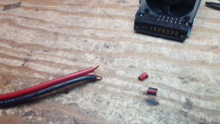
Now that the power supply has been modified to be turned on full time, we must device a method to bring out the 12VDC to connect to the equipment. In this example a 10awg wire with Anderson Powerpoles will be used.
1) Strip back about 3/8" of insulation from both the positive (red) and negative (black) leads.
