Uncategorized files
Showing below up to 50 results in range #121 to #170.
View (previous 50 | next 50) (20 | 50 | 100 | 250 | 500)
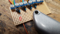
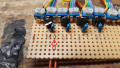
 4PPC output1 devicenet1 rxa soldered.jpg 1,024 × 576; 147 KB
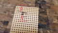
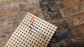
 4PPC output1 devicenet1 taped.jpg 1,024 × 576; 115 KB
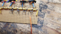
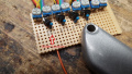
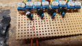
 4PPC output1 devicenet1 txa solder.jpg 1,024 × 576; 184 KB
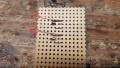
 4PPC output1 devicenet1 white heatshrink.jpg 1,024 × 576; 121 KB
 4PPC output1 devicent1 heatshrink applied.jpg 1,024 × 576; 123 KB
 4PPC output1 strip tin heathsrink.jpg 1,024 × 576; 94 KB
 4PPC output ribbon1 ptt ground pulled.jpg 1,024 × 576; 73 KB
 4PPC output ribbon1 rxa soldered.jpg 1,024 × 576; 141 KB
 4PPC output ribbon1 stripped tinned.jpg 1,024 × 576; 121 KB
 4PPC output ribbon1 txa soldered.jpg 1,024 × 576; 149 KB
 4PPC output ribbon2 soldered.jpg 1,024 × 576; 151 KB
 4PPC output ribbon2 soldered top.jpg 1,024 × 576; 100 KB
 4PPC output ribbon all bottom.jpg 1,024 × 576; 140 KB
 4PPC output ribbon all top.jpg 1,024 × 576; 114 KB
 4PPC outputall devicenetall taped.jpg 1,024 × 576; 126 KB
 4PPC perfboard attach.jpg 1,024 × 576; 117 KB
 4PPC perfboard test fit1.jpg 1,024 × 576; 190 KB
 4PPC perfboard test fit2.jpg 1,024 × 576; 71 KB
 4PPC ptt1 blue soldered heatshrink.jpg 1,024 × 576; 172 KB
 4PPC ptt1 blue soldered with heatshrink.jpg 1,024 × 576; 104 KB
 4PPC ptt1 blue stripped tinned.jpg 1,024 × 576; 175 KB
 4PPC ptt1 gpio line cut.jpg 1,024 × 576; 149 KB
 4PPC ptt1 gpio line tin soldered.jpg 1,024 × 576; 115 KB
 4PPC ptt1 gpio wire cut.jpg 1,024 × 576; 160 KB
 4PPC ptt1 gpio wire inserted.jpg 1,024 × 576; 113 KB
 4PPC ptt1 gpio wire through bent.jpg 1,024 × 576; 163 KB
 4PPC ptt1 gpio wire through soldered.jpg 1,024 × 576; 186 KB
 4PPC ptt1 lead trim bottom.jpg 1,024 × 576; 167 KB
 4PPC ptt1 lead trim top.jpg 1,024 × 576; 156 KB
 4PPC ptt1 lead trimed top.jpg 1,024 × 576; 102 KB
 4PPC ptt1 ptt wire cut.jpg 1,024 × 576; 119 KB
 4PPC ptt1 ptt wire inserted.jpg 1,024 × 576; 170 KB
 4PPC ptt1 solder.jpg 1,024 × 576; 152 KB
 4PPC ptt1 through bent.jpg 1,024 × 576; 159 KB
 4PPC ptt1 through soldered.jpg 1,024 × 576; 154 KB
 4PPC ptt2 installed bottom.jpg 1,024 × 576; 144 KB
 4PPC ptt2 installed top.jpg 1,024 × 576; 172 KB
 4PPC ptt all ground tin soldered.jpg 1,024 × 576; 122 KB
 4PPC ptt all soldered with heatshrink.jpg 1,024 × 576; 148 KB
 4PPC rpi3 4pin insulate.jpg 1,024 × 576; 185 KB
 4PPC rpi3 bottom.jpg 1,024 × 576; 128 KB
 4PPC rpi3 dc pins tinned.jpg 1,024 × 576; 192 KB
 4PPC rpi3 ethernet placement.jpg 1,024 × 576; 209 KB
 4PPC rpi3 gpio insulate1.jpg 1,024 × 576; 93 KB
 4PPC rpi3 gpio insulate2.jpg 1,024 × 576; 77 KB
 4PPC rpi3 gpio insulation down.jpg 1,024 × 576; 155 KB
 4PPC rpi3 gpio pins tinned.jpg 1,024 × 576; 192 KB
 4PPC rpi3 tape bottom1.jpg 1,024 × 576; 107 KB
 4PPC rpi3 tape bottom2.jpg 1,024 × 576; 93 KB
 4PPC rpi3 tape bottom3.jpg 1,024 × 576; 82 KB


