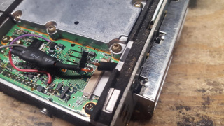
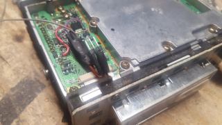
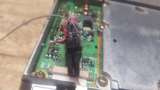
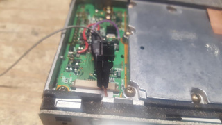
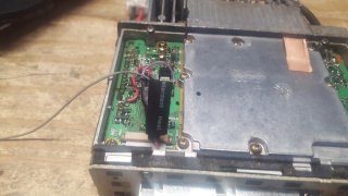
Modifying Kenwood TK-760(H)G/762(H)G/860(H)G/862(H)G/863G for Packet Service
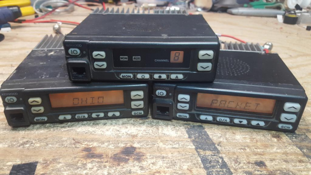
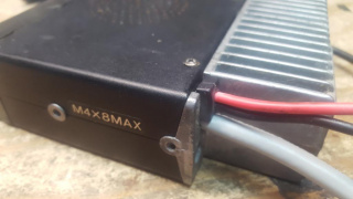
The Kenwood TK-760(H)G/762(H)G/860(H)G/862(H)G/863G are relatively low cost commercial radios that can be reprogrammed to work in the 2m and 70cm bands and depending on band and model are rated for 25-50w output. With a steady hand and fine tipped soldering iron, they can be modified for 1200-9600 baud service, VARA FM/FM Wide, including optional COR/COS signaling for hardware carrier detect or use in other services like Allstarlink, Echolink, SVXLink, Repeater controllers/remote base, etc. This guide wires them to the Kantronics DB-9 standard and is compatible with the 4 Port packet controller and NinoTNC, details to support adaptation to other interfaces to other interfaces is included.
| Model | Band | Channel Capacity | Output Power | Subband Splits |
| TK-760G | VHF High (2m) | 128 | 25W | 1 = 148-174 MHz, 2 = 136-162 MHz |
| TK-760HG | VHF High (2m) | 128 | 50W | 1 = 148-174 MHz, 2 = 136-162 MHz |
| TK-762G | VHF High (2m) | 8 | 25W | 1 = 148-174 MHz, 2 = 136-162 MHz |
| TK-762HG | VHF High (2m) | 8 | 50W | 1 = 148-174 MHz, 2 = 136-162 MHz |
| TK-860G | UHF (70cm) | 128 | 25W | 1 = 450-490 MHz, 2 = 485-512 MHz, 3 = 400-430 MHz |
| TK-860HG | UHF (70cm) | 128 | 40W | 1 = 450-490 MHz, 2 = 485-512 MHz, 3 = 400-430 MHz |
| TK-862G | UHF (70cm) | 8 | 25W | 1 = 450-490 MHz, 2 = 485-512 MHz, 3 = 400-430 MHz |
| TK-862HG | UHF (70cm) | 8 | 40W | 1 = 450-490 MHz, 2 = 485-512 MHz, 3 = 400-430 MHz |
| TK-863G | UHF (70cm) | 600 | 25W | 1 = 450-490 MHz |
A note on Bandsplits
The band splits are indicated differently between some documentation and what is actually printed on the radio. The labels on the radio seem to be numeric while the documentation references the letter K. Cross referencing the two:
K = 1
K2 = 2
K3 = 3
For VHF, the K(1) is the most common split, but both the K(1) and K2 splits cover all of 2m (144-148 MHz) without issue. For UHF, the K(1) split is also the most common split (450-490 MHz) and can usually cover at least 438-450 MHz, some of them will go down as low as 433 MHz with a simple VCO adjustment. The less common K2 split (485-512 MHz) is too far away from the 70cm band to be used and should be avoided except for part donors. The least common K3 split (400-430 MHz) can probably cover the lower portions of the 70cm band, possibly up to 440 or higher. We have not been able to obtain any of these to test, though they be may more available in proximity to Line A along the northern border of the USA and up in Canada where it is a commercial band. If you do end up with a K3 split and want a K split, please contact us to arrange a trade, we will cover shipping in both directions.
Required parts
1) Around 12" of 5 or more conductor ribbon cable, multicolor suggested
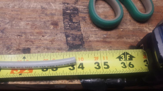
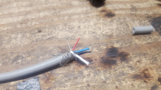
2) 34" of Devicenet 2 pair 22 gauge cable
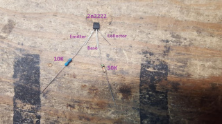
3) 2n2222 transistor or equivalent (Optional for COR logic inverter)
4) 10K resistor (Optional for COR logic inverter)
5) 50K resistor (Optional for COR logic inverter)
6) 1-2x 3 pin 2.54mm header, commonly available for Raspberry Pi and Arduino projects (Optional 1 for COR logic signaling enable/disable and/or changing TX audio between mic and modulator input)
7) 1-2x 2.54mm jumper (Optional for connections on item 6
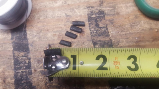
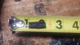
8) 1/8" heatshrink tubing
9) 1/4" heatshrink tubing
10) DB9 male, solder cup type suggested
11) DB9 hood, metal plated suggested
12) Electrical tape
13) Fine tipped soldering iron and solder
14) #1 or #2 Phillips screwdriver
15) Edge wire cutters
16) Box cutter or similar knife
17) Wire stripper for 22awg wire (optional)
18) Multimeter for testing (optional)
Modification Process
Prior to beginning any modification, it is best to test the radio for proper functionality. If this service was purchased used, there is a fair chance it is programmed to commercial frequencies. Reprogramming into the amateur bands is possible for the TK-760(H)G/762(H)G/860(H)G/862(H)G using the KPG-56D software which is available in both DOS and Windows. The TK-863G requires KPG-76D and is available only for Windows. In general, the VHF high band versions will work well into the 2m band with little or no adjustments needed to the VCO or receiver. The UHF versions (K split, 450-490 MHz) will often work without modification in the upper 10 MHz (440-450 MHz) and sometimes lower. Many of the UHF versions can go lower into the 70cm band by adjusting the VCO circuits. Some may go down as low as 433 MHz or possibly lower. It should be possible to add small amounts of parallel capacitance across the trimmer capacitors in the VCO section to pull it's range lower in frequency. This will likely be explored in the future.
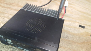
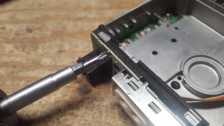
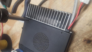
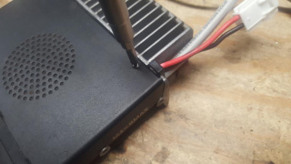
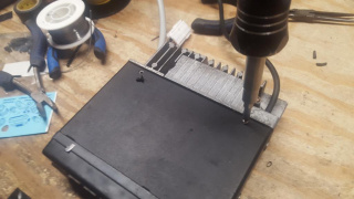
1) Open the top cover by removing the two rear screws near the heatsink
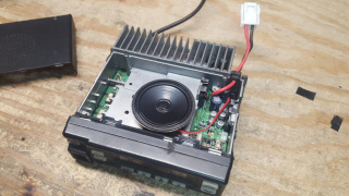
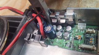
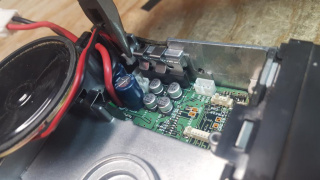
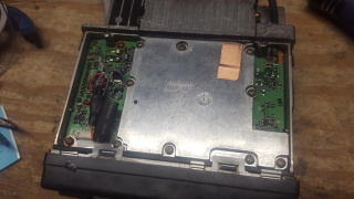
2) With the top cover removed, use a pair of pliars to gently pull out the speaker from the main board, setting the speaker aside for now.
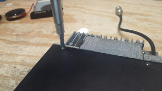
3) Flip the radio over and remove the two rear screws near the heatsink
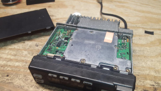
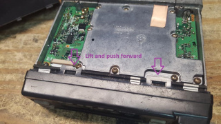
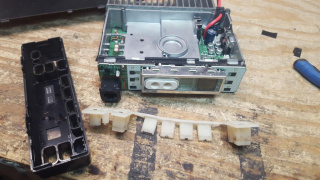
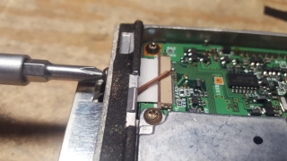
4) Gently lift up on the tabs on the faceplate and slide forward
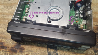
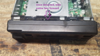
5) Flip the radio over and lift up on the tabs on the faceplate and slide forward
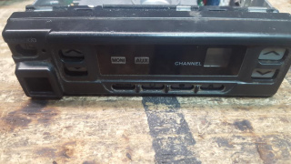
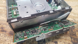
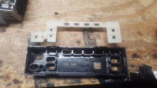
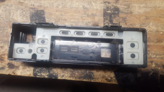
6) Pull the faceplate forward, there is a rubber membrane for the keys which may separate from the faceplate or remain in the faceplate. Separated membrane shown.
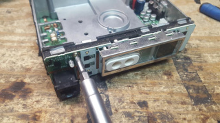
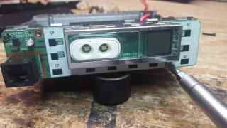
7) Remove the two faces which hold on the faceplate circuit board
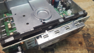
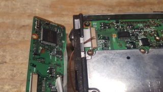
8) Gently pull the faceplate circuit board forward, it may be somewhat "stuck" to the chassis, be careful not to pull to hard which could damage the ribbon to the main board.
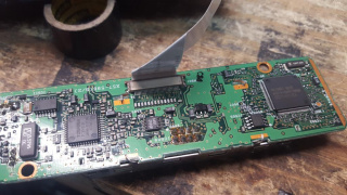
9) Lay the faceplate circuit board down, exposing the solder side
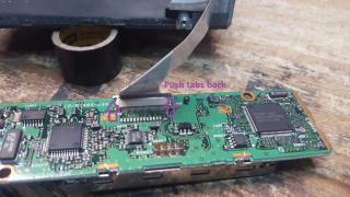
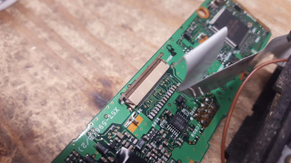
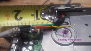
10) Carefully pull up the brown tabs on either side of where the ribbon cable locks into the faceplate circuit board
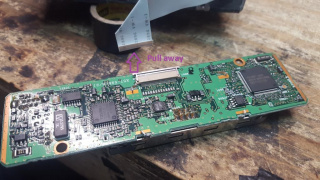
11) Pull the ribbon cable away from the faceplate circuit board.
12) Flip the faceplate circuit board to where the ribbon cable attachment faces down
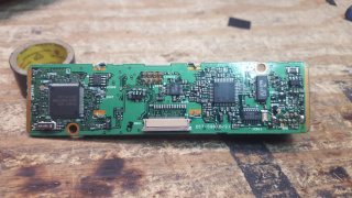
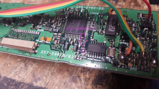
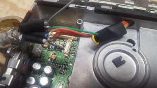
13) Our area of interest is on the bottom right side of the faceplate circuit board
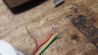
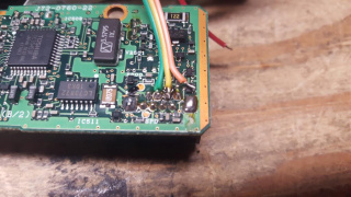
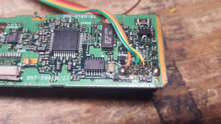
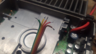
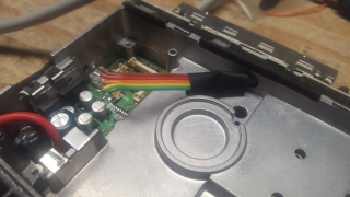
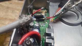
14) Cut about 5 inches of 5 conductor ribbon cable. If you want to have support for COR signaling strip back about 1/8" of all 5 wires, twist and tin. If you do not want to add COR support (not required for packet) strip back about 1/8" of 4 wires, leaving one unstripped or it can be removed completely. In this guide we will show COR support. Separate 2 of the 5 wires several inches, the separation of the remaining 3 can be left short. In this build
Green = PTT
Yellow = Mic Audio
Orange = Ground
Red = RX Audio (Discriminator)
Brown = COR (Active high)
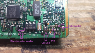
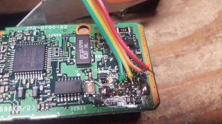
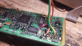
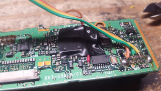
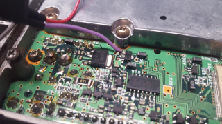
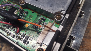
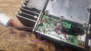
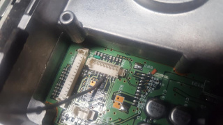
15) Solder the PTT wire to the second from left pin behind the microphone jack
16) Solder the Mic Audio wire to the third from left pin, next to the PTT wire
17) Repositioning the wire, solder the ground wire to the grounding pad below the microphone jack to the left
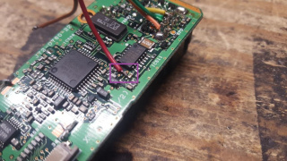
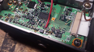
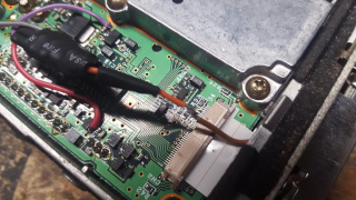
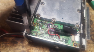
18) Carefully apply solder to one of the two surface mount resistors that carry Discriminator audio
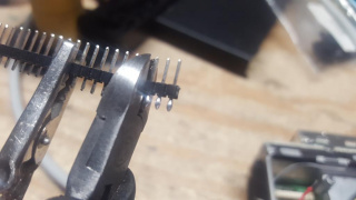
19) Add a bit more solder to the tip of the RX audio wire. Try to make it look a bit like a rain drop.
20) Carefully hold the tinned RX audio wire over the surface mount resistor and apply heat, the goal is to melt the extra solder to flow over the resistor
21) Using electrical tape or some other method, apply strain relief on the RX audio wire to try and keep any mechanical stress off the solder joint.
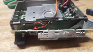
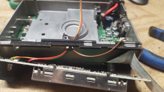
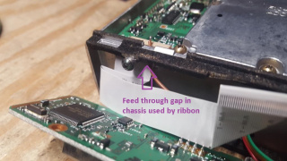
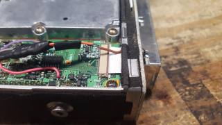
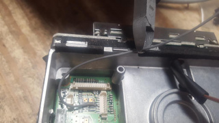
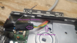
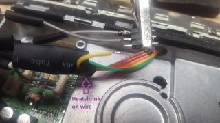
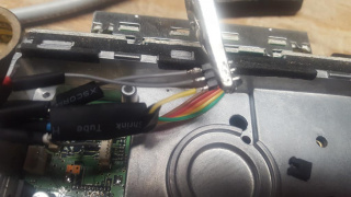
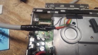
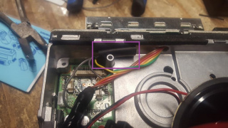
22) Feed the ribbon cable through the small hold in the top/center of the chassis to the main body of the radio. The COR wire is still "floating" at this point.
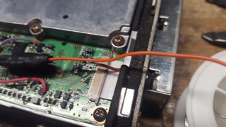
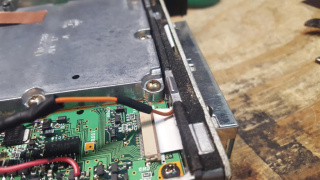
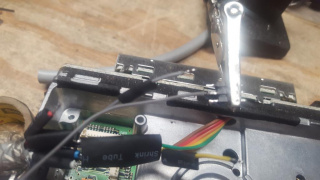
22) Pull away the COR wire, this will be fed to the opposite corner of the face plate to be passed next to the ribbon cable to the under side of the radio. This will split about where the ribbon cable passes through to the main body of the radio.
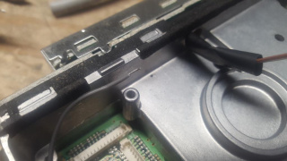
23) Feed the COR wire through the small opening in the chassis that passes the thin ribbon cable between the face plate and main board
24) Side the face plate circuit board back towards the main chassis of the radio, lining up the ribbon cable with the attachment point.
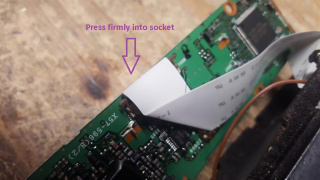
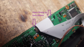
25) Slide the ribbon cable back into position. Be sure to press inward to try and get the ribbon cable fully seated.
26) Gently press down on the brown tabs on either side to lock the ribbon cable in place.
27) Press the faceplate circuit board back against the main chassis. Be careful not to pinch any of the wires we soldered in the process and that the COR wire remains visible in the under side of the radio. Reattach the first screw holding the faceplate circuit board.
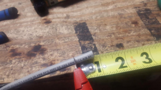
28) Flip the radio over and attach the second screw holding the faceplate circuit board.
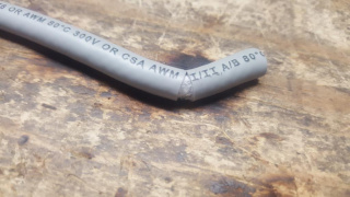
29) If COR signaling is desired, flip the radio over putting the side with the COR wire fed to the front. This is where our COR circuit will be attached. If COR signaling is not desired, skip to step 71
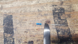
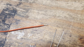
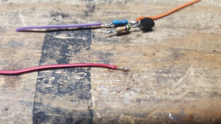
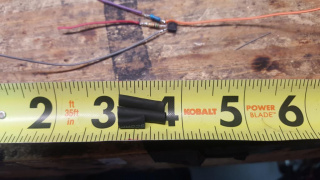
30) Take a 2n2222 or equivalent transistor, 10k resistor and 50k resistor. These will allow us to invert the COR logic, which is natively active low to be active high. We want to attach the 10k resistor to the emitter and 50k resistor to the base.
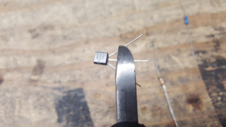
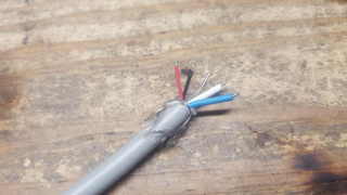
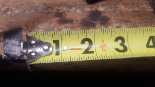
31) Trim the leads on the 2n2222 to about 1/4".
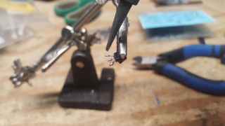
32) Apply solder to all 3 leads on the 2n2222
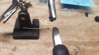
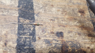
33) Trim one of the leads on the 50k resistor to about 1/4" and tin the lead.
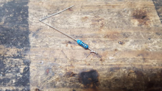
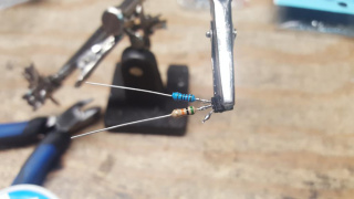
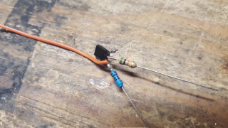
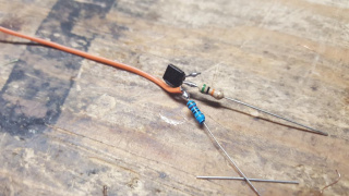
34) Solder the 50k resistor to the base (center wire) of the 2n2222.
File:TK n6ng COR 50k to 2n2222.jpg
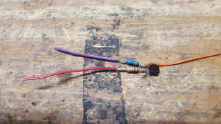
35) Trim one of the leads on the 10k resistor about 1/4" and tin the lead.
36) Solder the 10k resistor to the emitter (left of base pictured) of the 2n2222.
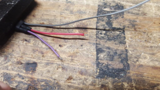
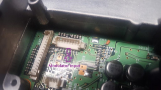
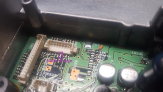
37) Take about 2" of single wire from the ribbon cable to be use for COR logic inverter output, strip back about 1/4" but do not tin. In this build we will use an orange wire.
38) Take the stripped end of the COR logic inverter output and wrap it around the soldered connection between the 10k resistor and 2n2222 emitter.
39) Solder the COR logic inverter output wire around the 2n2222 and 10k resistor junction as shown.
40) Trim both the 10k and 50k resistor legs about 1/4" on the opposing lead that is soldered to the 2n2222.
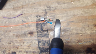
41) Take about 2" of single wire from the ribbon cable to be used for the 5VDC feed, strip back about 1/4" and tin. In this build we will use a purple wire.
File:TKn6ng-COR 5v wire strip tin.jpg
42) Solder the COR logic inverter 5v input to the 10k resistor.
File:TKn6n-COR 5v to 10k resistor.jpg
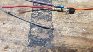
43) Take about 3" of single wire from the ribbon cable to be used for the COR signal feed, strip back about 1/4" and tin. In this build we will use a red wire.
44) Solder the COR signal input to the 50k resistor.
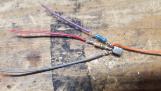
45) Take about 4" of single wire from the ribbon cable to be use for the COR inverter circuit ground, strip back about 1/4" and tin. In this build we will use a grey wire.
46) Solder the COR ground to the collector of the 2n2222 (only lead without a resistor attached)
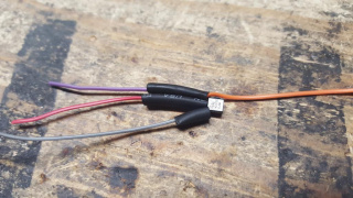
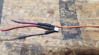
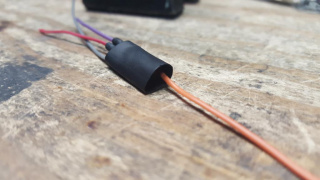
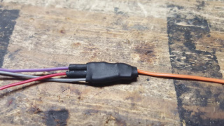
47) Cut two 3/4" sections and one 3/8" section of 1/8" heatshrink tubing
48) Slide the two 3/4" sections over both leads that have resistors and the 3/8" section over the junction of the 2n2222 collector and ground wire.
49) Apply heat to the circuit, making sure the heatshrink tubing stays as close to the 2n2222 as possible.
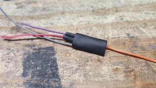
50) Cut one 3/4" section of 1/4" heatshrink tubing and slide over the circuit, leaving the heatshrink just past the top of the 2n2222
51) Apply heat to the circuit, securely covering the 2n2222
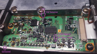
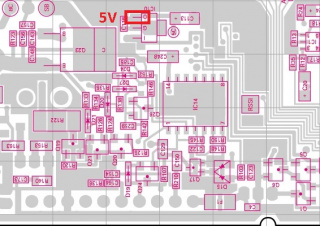
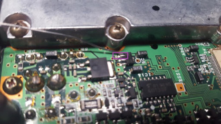
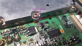
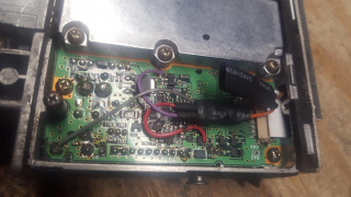
52) Returning to the radio, apply a small amount of solder to the left most/output leg of IC10 near the 5C label, in the center of the main board next to the ribbon cable.
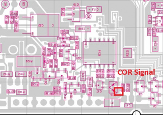
53) Apply a small amount of solder to the left anode of D15 near the outside of the radio.
54) Strip and tin about 1/8" from the ends of the 5v, COR signal and ground wires. The heat may melt off some of the insulation and additional trimming may be required to get the desired short lengths.
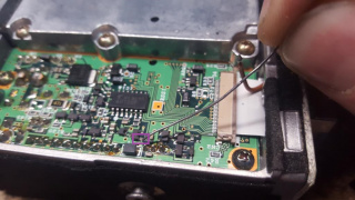
55) Solder the 5v wire to IC10/NJM78L05UA 5V regulator's output pin closest to the center of the radio.
56) Solder the COR signal wire to the outer input of D15/DAN235K near the output of the radio.
57) Take the COR logic inverter output wire and run it towards the front of the radio, it should overlap with the COR wire we fed through earlier
58) Strip about 1/4" of insulation and tin the output wire.
59) Cut about 3/8" of 1/8" heatshrink tubing and slide over the COR logic inverter output wire.
60) If you want the COR logic to be permanently connected, solder the COR logic output wire to the COR wire that feeds to the front of the radio. If you do not, skip to step 62.
61) Slide the 3/8" of 1/8" heatshrink tubing over the COR logic output wire junction and heat up.
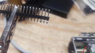
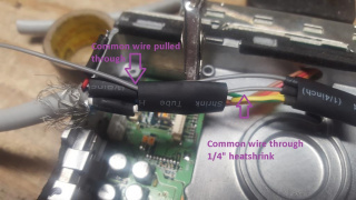
62) If you want to be able to enable or disable COR signaling via hardware jumper, take a single row of 2.54mm header pins and tin 3 consecutive pins. This is needed if you want to use this radio with a CM108/RA/URI type interface that supports COR signaling on Windows. With the COR connected all the time to that type interface, the COR signal will mute the microphone input whenever a signal is present.
63) Trim off the prepared 3 pins from the header pins
64) Attach the COR logic output wire to one of the outside pins of the 3 pin header.
65) Slide about 3/8" of 1/8" heatshrink over the COR wire leading to the front of the radio to the center pin of the 3 pin header.
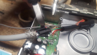
66) Slide the heatshrink tubing up the COR logic output and front wires, covering both the center and unused pins with the output wire heatshrink tube.
67) Take a 2.54mm jumper (this can be scavanged from old computer harddrives and other devices) and place it over the pins connected to the COR logic output and front wires and apply heat.
In this position, COR output is connected and the radio will send a 5V signal whenever a signal is present.
To disable this connection, move the jumper over to the pin which is not connected.
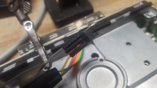
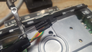
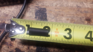
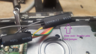
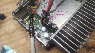
68) Take about 1" of 1/4" heatshrink tubing and slide it over the header/jumper assembly. Do not heat this, the heatshrink should provide a friction fit over the jumper to safely insulate the jumper while allowing its position to be changed at some future time.
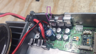
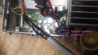
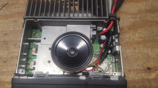
69)Take the COR logic ground wire, lay it out to reach the back corner of the radio, trim to length to reach the large ground solder pad in the corner.
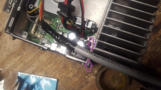
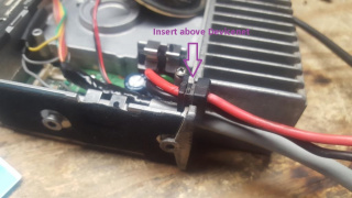
70) Strip and tin about 1/4" of the ground wire, soldering it to the rear solder pad. This concludes the COR logic setup.
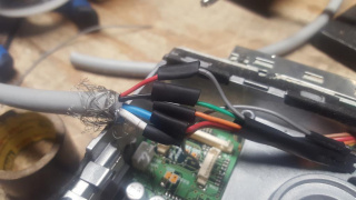
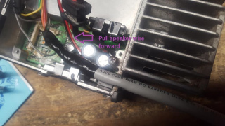
71) Flip the radio so it's top is facing up, separate, strip about 1/8" and tin all 5 wires. If you skipped the COR circuit, strip and tin all 4.
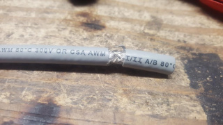
72) Cut about 34" of Devicenet cable to be used to bring signaling out of the radio.
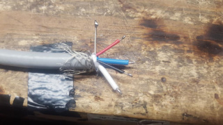
73) Carefully cut the jacket off the devicenet cable about 5/8" from the end.
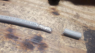
74) Bend the Devicenet cable back and forth, this should cause the outer jacket to separate, exposing the braid.
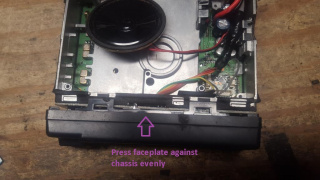
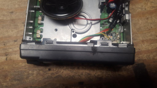
75) Rocking the devicenet cable back and forth and making any needed small cuts to break it free, pull the 5/8" section of outer jacket off.
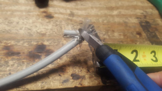
76) Fold back the outer braid from the Devicenet cable and trim away any of the nylon strands inside the braid.
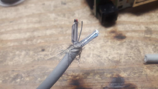
77) Separate the two wire pairs and bare ground lead.
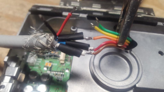
78) Pull away the foil shield that is covering both wire pairs. A small cut in the foil may be needed to ease it's removal. When removed, separate all 5 wires. In this build and recommended if your devicenet colors match:
Red = TX Audio
Black = PTT
Blue = RX Audio
White = COR
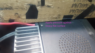
Bare = Ground
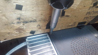
79) Strip about 1/8" of all 4 and tin all 5 wires. If you omit the COR circuit, do not strip or tin the white wire.
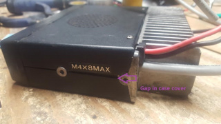
80) Take five 3/8" long sections of 1/8 heatshrink tubing. and one 1" long section of 1/4" heatshrink tubing.
81) Slide the 1" long 1/4" heatshrink tubing over the ribbon cable that runs to the front of the radio.
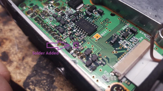
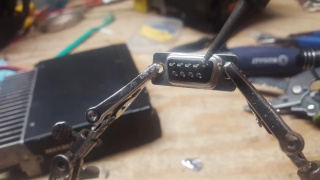
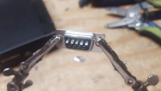
82) To provide optional input to the modulator (needed for 4800 and 9600 baud packet as well as VARA FM WIDE), locate CN4 on the side of the radio where the DC power cable exits. This is an 8 pin header and we are interested in pin 4. This is the only pin that has the surface mount capacitor near by.
83) Carefully take a soldering iron and solder and create solder bridge between the pin on the connector and surface mount capacitor. These two components are already shorted, this bridge gives a larger area to solder the wire to be brought out of the radio.
84) Take about 5" of single wire from the ribbon cable, strip about 1/8" and tin the end to be used for the modulator input tap. In this build this wire is gray.
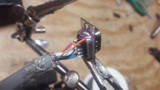
85) Carefully solder the modultor input wire to the solder bridge created in step 83.
86) Leave plenty of extra wire to try and minimize mechanical stress on the connection, run it around the outside wall of the chassis and trim about 1/2" past the internal cylinder on the inside of the chassis.
87) Strip and tin about 1/8" of the modulator wire.
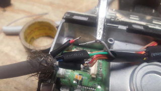
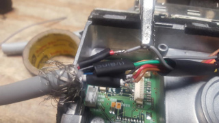
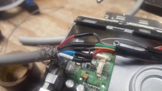
88) Slide one of the 3/8" of 1/4" heatshrink tubes over the white wire and solder the white devicenet wire to the COR circuit wire(brown in this build). If you omit the COR circuit, set aside the heatshrink and leave the devicenet white wire for now.
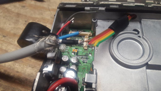
89) Slide one of the 3/8" of 1/4" heatshrink tubes over the blue wire and solder the blue devicenet wire to the RX audio wire (red in this build).
90) Slide one of the 3/8" of 1/4" heatshrink tubes over the bare wire and solder the bare devicenet wire to the ground wire (orange in this build).
91) Slide one of the 3/8" of 1/4" heatshink tubes over the black wire and solder the black devicenet wire to the PTT wire (green in this build).
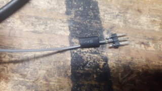
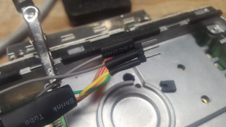
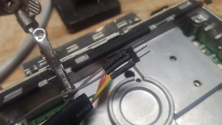
92) If you opted to make a modulator input, take a 2.54mm header pin and tin 3 consecutive pins.
93) Cut the 2.54mm 3 pin header which has it's pins tinned.
94) Cut three 3/8" sections of 1/4" heatshrink tubing.
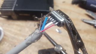
95) Take about 3" of single wire from the ribbon cable, strip about 1/8" and tin the end to be used for the TX input switch (microphone or modulator). In this build this wire is gray.
96) Slide one of the 3/8" of 1/4" heatshrink tubes over the input wire and solder it to the center pin of the 3 pin header.
97) Separate about 1" of the mic audio line (yellow) that runs to the front of the radio.
98) Feed the microphone audio line back through the heatshrink tubing.
99) Pull the 1/4" heatshrink tubing towards the solder junctions, exposing the mic audio line.
100) Slide one of the 3/8" of 1/4" heatshrink tubes over the modulator input wire.
101) Solder the modulator input wire to one of the outside pins of the 3 pin header.
102) Slide one of the 3/8" of 1/4" heatshrink tubes over the microphone input wire.
103) Solder the microphone input wire to the remaining outside pin on the 3 pin header.
104) Slide all 3 pieces of 3/8" heatshrink up against the 3 pin header.
105) Apply heat, carefully trying to shield the 1/4" heatshrink still over the remainder of the ribbon cable.
106) Attach a computer type jumper to the header.
In this position, input audio is sent to the microphone input. This is suitable for 1200 and 2400 baud, VARA FM as well as most NBEMS/fldigi type modes.
In this position, input audio is sent to the modulator input. This is suitable for 4800 and 9600 baud and VARA FM wide.
107) Cut one 1" long section of 1/4" heatshrinkg tubing.
108) Slide this over the TX audio input selection jumper. Do not heat this, the heatshrink should provide a friction fit over the jumper to safely insulate the jumper while allowing its position to be changed at some future time.
109) Slide the common (center) wire from the TX audio selection jumper through the heatshrink tube which covers the ribbon cable.
110) Slide the 1/4" heatshrink tubing back across the ribbon cable, cut the common TX audio wire to length in order to solder to the red Devicenet wire.
111) Trim and tin about 1/8" of the common TX audio wire, side a 3/8" length of heatshrink tube over the red Devicenet wire.
112) Solder the red Devicenet wire to the common TX wire (grey in this build). If you omit the modulator input, solder red Devicenet wire to the microphone input wire (yellow).
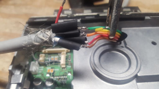
113) Slide all heatshrinks over the junctions between the Devicenet and ribbon cable. If you omitted the COR circuit, place heatshrink over the end of the white Devicenet cable, allowing the heatshrink to extend past the end of the white wire.
114) Apply heat to the solder junctions, carefully try to shield heat from the 1/4" heatshrink slide down the ribbon cable.
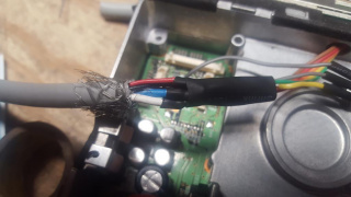
115) Carefully slide the 1/4" heatshrink tubing up the ribbon cable and over the soldered/heatshrink bundle. This may be a tight fit, it is possible to slightly strech the heatshrink using needle nose pliers or similar method. Ideally the outer 1/4" heatshrink sould cover all the other pieces of heatshrink.
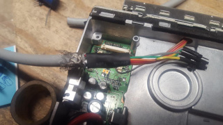
116) Apply heat to this heatshrink to keep it in place, then wrap electrical tape starting near the end of the heatshrink on the ribbon cable and covering up all braid wires on the Devicenet cable.
117) Pull the DC power cable out of the groove in the main chassis, moving it towards the middle of the radio.
118) Reinstall the internal speaker, the jack near two large capacitors
119) Press the Devicenet cable into the DC power groove. This is going to be a tight fit.
120) It may be nessesary to reroute the speaker wire from in between the capacitors to around the front to allow clearance for the devicenet cable.
121) Double check the TX audio input jumper, select which input you want audio to be delivered (microphone or modulator). Once selected, slide the 1/4" heatshrink tube over the jumper and tuck it behind the cylinder on the main chassis towards the front of the radio.
122) Move the DC power cable back into the groove, this will not fit initially since the Devicenet cable is sharing this space.
123) If the front rubber membrane separated during disassembly, line it back up and place it back into the faceplate.
124) Carefully slide the faceplate to the front of the radio, try to keep the faceplate square to the radio chassis so it can snap on evenly.
125) Slide the speaker back into position, there is a section in the chassis with two circles where the speaker is designed to rest.
126) Take the top cover of the radio (it has holes for the speaker output and place it on the top of the radio. It will not fit initially over the side with the power and Devicenet cable.
127) Apply slight pressure to the top cover and attach the case screw opposite of the power and devicenet cable.
128) Applying slight pressure on the opposite side, try to get the other screw to "bite". We don't want to fully tighten this way as it may bend the cover slightly.
129) Flip the radio over looking at the bottom, if the COR circuit was installed, double check that the jumper is in the desired position and verify the 1/4" heatshrink covers the jumper.
130) Reattach the bottom cover, this cover is one solid piece of metal and has no holes for a speaker. Apply both screws and turn until tight.
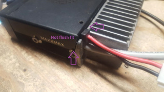
131) Flipping the radio back over, examine the top of the case where the power and devicenet cable exits. This will probably not be flush.
132) Place the radio under a flat and heavy surface (workbench works well) and push upwards, this will cause the devicenet cable to push downward and the rubber grommet of the power cable to spread out. This will make the case flush with the radio and the screw head should appear raised.
133) Finish tightening the top case screw near the power and Devicenet cable.
134) Check the side of the case to ensure it's made a firm seal with no major gaps between top and bottom covers.
135) Remove about 5/8" of the Devicenet cable which is outside the radio, folding the braid back, removing the foil, separating the wires and tinning all 5 wires as completed in steps 73-80. If the COR circuit was omitted, we will still strip and tin the white wire to keep it from floating in the DB9 connector.
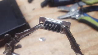
136) Take a DB9 solder type male connector with the 5 pin row facing up. Apply solder to pin 1.
137) Repeat applying solder to pins 2, 3 and 5.
138) Flip the DB9 connector and apply solder to pin 6.
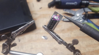
139) Moving the DB9 onto it's side, apply solder to the shell of the DB9 next to pins 1 and 6.
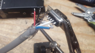
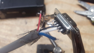
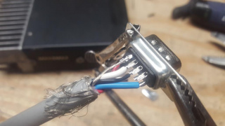
140) Taking the Devicenet cable, solder the white wire (COR) to DB9 pin 2.
141) Solder the black wire (PTT) to DB9 pin 3.
142) Solder the red wire (TX Audio) to DB9 pin 1.
143) Solder the blue wire (RX Audio) to DB9 pin 5
144) Flip the DB9 over and solder the bare wire to pin 6
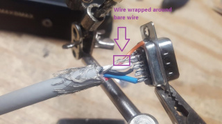
145) Take about 3/4" of single wire from the ribbon cable to be used for the DB9 shell ground, strip back about 1/8" and tin on side and strip about 1/4" on the other, but do not tin. In this build we will use a orange wire.
146) Take the 1/8" tinned portion of the shell ground wire and solder it to the DB9 shell.
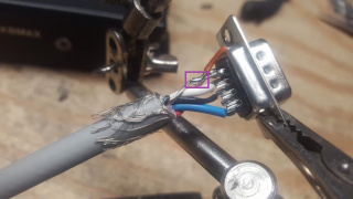
147) Take the 1/4" stripped portion of the shell ground wire and wrap it around the bare wire.
148) Solder the wrapped shell ground wire to the bare wire.
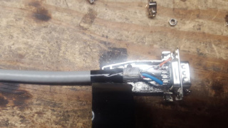
149) Place the Devicenet cable in a suitable DB9 hood, metal plated recommended. About 1/4" past where the hood ends, wrap with electrical tape. This will securely hold the Devicenet cable in the hood and relieve the soldered connections of any mechanical stress. Using Scotch 33+ tape, 4 or 5 turns seems to work well.
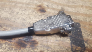
150) Attach the DB9 hood over the DB9, the wraps of electrical tape will make this a tight fit. Slide the locking screws through the front, then add the screws and nuts to fully secure the hood.
Post modification testing
Multimeter + Second radio testing:
1) Take a continuity tester and verify a DC short between the DB9 pin number 6 and the radio chassis as well as DB9 shell
2) Measure for DC voltage across DB9 pin number 3 (PTT). If present, attach suitable antenna or dummy load to modified and short pin 3 to the DB9 shell or DB9 pin 6, this should cause the radio to transmit.
3) Measure AC voltage across DB9 pin 5. This is discriminator receive audio and will be a fairly steady AC voltage with no signal present. If AC voltage is measured and another transmitter is available, transmit a dead carrier with no audio, this should cause the AC voltage to drop significantly if not fully near 0 volts indicating the receiver has a full quieting signal.
4) If the COR circuit was added and COR enable jumper was placed, measure DC voltage across DB9 pin number 2. With no signal present, the DC voltage should be near 0. Using either the MON function on the front of the radio OR using a secondary transmitter on the frequency, open up the squelch and this pin should read about 5VDC.
5) Create a short between DB9 pin numbers 1 (TX Audio) and 5 (RX Audio). On an secondary receiver, tune to the modified radio transmit frequency. Short DB9 pin 3 to ground either on the DB9 shell or DB9 pin 6. This should cause the radio to transmit and the secondary receiver should pick up a signal with static. Momentarily break the short between DB9 pin numbers 1 and 5, this should turn the signal from full quieting and static off the discriminator.
Soundcard interface/packet controller/hardware TNC testing:
1) Attach the radio to a compatible interface. If the interface/TNC does not use the Kantronics DB9 standard, a suitable adapter will need to be made. To review, the DB9 pinout is:
DB9 Pin 1 = TX Audio
DB9 Pin 2 = COR (Active High) - if built and enabled
DB9 Pin 3 = PTT (Active Low)
DB9 Pin 5 = RX Audio
DB9 Pin 6 = Ground
2) Place the modified radio on a known packet frequency. If none is available on VHF, a good candidate for traffic is the national APRS frequency, 144.390 MHz in North America, 144.80 in Europe. Optionally turn up the volume on the radio and listen for packet bursts to come out of the speaker. When a packet burst is heard, check the interface/TNC for a successful decode.
3) Placing an auxiliary receiver on the radio transmit frequency, issue an outbound connection and listen for a packet burst on the auxiliary receiver. If no other station exists, a dummy call can be used:
C XX1XX
Please pass along any modification questions or suggestions regarding this modification process.
