Uncategorized files
Showing below up to 100 results in range #101 to #200.
View (previous 100 | next 100) (20 | 50 | 100 | 250 | 500)
 4PPC ground bus third prep.jpg 1,024 × 576; 181 KB
 4PPC ground bus third soldered.jpg 1,024 × 576; 172 KB
 4PPC ground bus wire cut.jpg 1,024 × 576; 105 KB
 4PPC ground inserted.jpg 1,024 × 576; 190 KB
 4PPC mount wire bent gpio.jpg 1,024 × 576; 87 KB
 4PPC mount wire left stripped.jpg 1,024 × 576; 83 KB
 4PPC mount wire left wrapped.jpg 1,024 × 576; 81 KB
 4PPC mount wire right stripped.jpg 1,024 × 576; 77 KB
 4PPC mount wire right wrapped.jpg 1,024 × 576; 64 KB
 4PPC mount wire short check.jpg 1,024 × 576; 109 KB
 4PPC orange yellow all complete.jpg 1,024 × 576; 122 KB
 4PPC orange yellow heatshrink solder.jpg 1,024 × 576; 173 KB
 4PPC orange yellow soldered with heatshrink.jpg 1,024 × 576; 96 KB
 4PPC orange yellow strip tin.jpg 1,024 × 576; 140 KB
 4PPC output1 devicenet1 1 4 heatshrink applied.jpg 1,024 × 576; 134 KB
 4PPC output1 devicenet1 1 4 slid1.jpg 1,024 × 576; 198 KB
 4PPC output1 devicenet1 1 4 slid2.jpg 1,024 × 576; 127 KB
 4PPC output1 devicenet1 ground soldered.jpg 1,024 × 576; 196 KB
 4PPC output1 devicenet1 heatshrink white pinch.jpg 1,024 × 576; 212 KB
 4PPC output1 devicenet1 ptt soldered.jpg 1,024 × 576; 169 KB
 4PPC output1 devicenet1 rxa soldered.jpg 1,024 × 576; 147 KB
 4PPC output1 devicenet1 taped.jpg 1,024 × 576; 115 KB
 4PPC output1 devicenet1 txa solder.jpg 1,024 × 576; 184 KB
 4PPC output1 devicenet1 white heatshrink.jpg 1,024 × 576; 121 KB
 4PPC output1 devicent1 heatshrink applied.jpg 1,024 × 576; 123 KB
 4PPC output1 strip tin heathsrink.jpg 1,024 × 576; 94 KB
 4PPC output ribbon1 ptt ground pulled.jpg 1,024 × 576; 73 KB
 4PPC output ribbon1 rxa soldered.jpg 1,024 × 576; 141 KB
 4PPC output ribbon1 stripped tinned.jpg 1,024 × 576; 121 KB
 4PPC output ribbon1 txa soldered.jpg 1,024 × 576; 149 KB
 4PPC output ribbon2 soldered.jpg 1,024 × 576; 151 KB
 4PPC output ribbon2 soldered top.jpg 1,024 × 576; 100 KB
 4PPC output ribbon all bottom.jpg 1,024 × 576; 140 KB
 4PPC output ribbon all top.jpg 1,024 × 576; 114 KB
 4PPC outputall devicenetall taped.jpg 1,024 × 576; 126 KB
 4PPC perfboard attach.jpg 1,024 × 576; 117 KB
 4PPC perfboard test fit1.jpg 1,024 × 576; 190 KB
 4PPC perfboard test fit2.jpg 1,024 × 576; 71 KB
 4PPC ptt1 blue soldered heatshrink.jpg 1,024 × 576; 172 KB
 4PPC ptt1 blue soldered with heatshrink.jpg 1,024 × 576; 104 KB
 4PPC ptt1 blue stripped tinned.jpg 1,024 × 576; 175 KB
 4PPC ptt1 gpio line cut.jpg 1,024 × 576; 149 KB
 4PPC ptt1 gpio line tin soldered.jpg 1,024 × 576; 115 KB
 4PPC ptt1 gpio wire cut.jpg 1,024 × 576; 160 KB
 4PPC ptt1 gpio wire inserted.jpg 1,024 × 576; 113 KB
 4PPC ptt1 gpio wire through bent.jpg 1,024 × 576; 163 KB
 4PPC ptt1 gpio wire through soldered.jpg 1,024 × 576; 186 KB
 4PPC ptt1 lead trim bottom.jpg 1,024 × 576; 167 KB
 4PPC ptt1 lead trim top.jpg 1,024 × 576; 156 KB
 4PPC ptt1 lead trimed top.jpg 1,024 × 576; 102 KB
 4PPC ptt1 ptt wire cut.jpg 1,024 × 576; 119 KB
 4PPC ptt1 ptt wire inserted.jpg 1,024 × 576; 170 KB
 4PPC ptt1 solder.jpg 1,024 × 576; 152 KB
 4PPC ptt1 through bent.jpg 1,024 × 576; 159 KB
 4PPC ptt1 through soldered.jpg 1,024 × 576; 154 KB
 4PPC ptt2 installed bottom.jpg 1,024 × 576; 144 KB
 4PPC ptt2 installed top.jpg 1,024 × 576; 172 KB
 4PPC ptt all ground tin soldered.jpg 1,024 × 576; 122 KB
 4PPC ptt all soldered with heatshrink.jpg 1,024 × 576; 148 KB
 4PPC rpi3 4pin insulate.jpg 1,024 × 576; 185 KB
 4PPC rpi3 bottom.jpg 1,024 × 576; 128 KB
 4PPC rpi3 dc pins tinned.jpg 1,024 × 576; 192 KB
 4PPC rpi3 ethernet placement.jpg 1,024 × 576; 209 KB
 4PPC rpi3 gpio insulate1.jpg 1,024 × 576; 93 KB
 4PPC rpi3 gpio insulate2.jpg 1,024 × 576; 77 KB
 4PPC rpi3 gpio insulation down.jpg 1,024 × 576; 155 KB
 4PPC rpi3 gpio pins tinned.jpg 1,024 × 576; 192 KB
 4PPC rpi3 tape bottom1.jpg 1,024 × 576; 107 KB
 4PPC rpi3 tape bottom2.jpg 1,024 × 576; 93 KB
 4PPC rpi3 tape bottom3.jpg 1,024 × 576; 82 KB
 4PPC rpi3 tape bottom4.jpg 1,024 × 576; 74 KB
 4PPC rpi3 tape bottom5.jpg 1,024 × 576; 76 KB
 4PPC top leads front.jpg 1,024 × 576; 117 KB
 4PPC wrt54g antenna attached.jpg 1,024 × 576; 119 KB
 4PPC wrt54g bottom.jpg 1,024 × 576; 79 KB
 4PPC wrt54g case screw removal.jpg 1,024 × 576; 162 KB
 4PPC wrt54g case top install.jpg 1,024 × 576; 71 KB
 4PPC wrt54g case top on.jpg 1,024 × 576; 123 KB
 4PPC wrt54g devicenet1 feed.jpg 1,024 × 576; 92 KB
 4PPC wrt54g devicenet feed all.jpg 1,024 × 576; 125 KB
 4PPC wrt54g drill hole1.jpg 1,024 × 576; 84 KB
 4PPC wrt54g drill hole all.jpg 1,024 × 576; 90 KB
 4PPC wrt54g ethernet cover1.jpg 1,024 × 576; 91 KB
 4PPC wrt54g ethernet cover2.jpg 1,024 × 576; 76 KB
 4PPC wrt54g ethernet pins bottom.jpg 1,024 × 576; 158 KB
 4PPC wrt54g face removal.jpg 1,024 × 576; 111 KB
 4PPC wrt54g face removed.jpg 1,024 × 576; 113 KB
 4PPC wrt54g face slide on1.jpg 1,024 × 576; 88 KB
 4PPC wrt54g face slide on2.jpg 1,024 × 576; 92 KB
 4PPC wrt54g front.jpg 1,024 × 576; 88 KB
 4PPC wrt54g powerup test.jpg 1,024 × 576; 198 KB
 4PPC wrt54g top removed.jpg 1,024 × 576; 128 KB
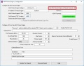 AGW Packet Engine Configuration Remote Computer.jpg 778 × 613; 118 KB
 Access Bullseye.png 744 × 658; 282 KB
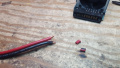 DPEx950 10awg stripped.jpg 1,024 × 576; 83 KB
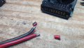 DPEx950 10awg tinned.jpg 1,024 × 576; 103 KB
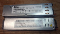 DPEx950 1950 2950 supplies.jpg 1,024 × 576; 108 KB
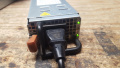 DPEx950 1950 powered on.jpg 1,024 × 576; 80 KB
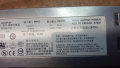 DPEx950 1950 specs.jpg 1,024 × 576; 110 KB
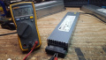 DPEx950 1950 voltage.jpg 1,024 × 576; 107 KB


